
Yu-tong MENG, Ming-xu PIAO, Qi WANG. Design of Refractive Diffraction Hybrid Annular Aperture Ultrathin Imaging Optical System[J]. Acta Photonica Sinica, 2019, 48(12): 1211003
- Acta Photonica Sinica
- Vol. 48, Issue 12, 1211003 (2019)
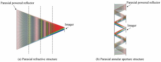
Fig. 1. 环形孔径超薄成像光学系统原理结构示意图Structure schematic diagram of ultrathin annular aperture imaging optical system
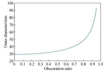
Fig. 2. 环形孔径超薄成像系统外直径和遮拦比关系Diagram of outer diameter and obscuration ratio of ultrathin annular aperture imaging system
Fig. 3. 环形孔径超薄成像系统初始结构调制传递函数Initial structure modulation transfer function of ultrathin annular aperture imaging system
Fig. 4. 环形孔径超薄成像系统初始结构的点列图和倍率色差Initial structure geometric of ultrathin annular aperture imaging system spot diagramand chromatic aberration
Fig. 5. 折衍射混合环形孔径超薄成像系统结构Structure of refractive diffraction hybrid ultrathin annular aperture imaging optical system
Fig. 6. 优化后折衍射混合环形孔径超薄成像系统的点列图和倍率色差Comparison of lateral color between the initial structure and optimized refractive diffraction hybrid ultrathin annular aperture imaging optical system
Fig. 7. 折衍射混合环形孔径超薄成像系统调制传递函数MTF of the designed refractive diffraction hybrid ultrathin annular aperture imaging optical system
Fig. 8. 折衍射混合环形孔径超薄成像系统衍射面特征参量曲线Characteristic parameter curve diffraction plane of refractive diffraction hybrid ultrathin annular aperture imaging optical system
Fig. 9. 折衍射混合环形孔径超薄成像系统不同温度下的MTF曲线MTF curves of refractive diffraction hybrid ultrathin annular aperture imaging optical system
Fig. 10. 折衍射混合环形孔径超薄成像系统不同温度下的倍率色差Lateral color aberration of refractive diffraction hybrid ultrathin annular aperture imaging optical system
|
Table 1. Size comparison of ultrathin annular aperture imaging optical system and F/1.2 traditional optical system with focal length 35 mm
|
Table 2. Design index of ultrathin annular aperture imaging system
|
Table 3. Initial structural parameters of ultrathin annular aperture imaging system
|
Table 4. Parameters of optimized refractive diffraction hybrid ultrathin annular aperture imaging optical system
| |||||||||||||||||||||||||||||||
Table 5. Aspheric coefficient of refractive diffraction hybrid ultrathin annular aperture imaging optical system
|
Table 6. Fabrication tolerance for refractive diffraction hybrid ultrathin annular aperture imaging optical system
| |||||||||||||||||||||||||||
Table 7. MTF values of all fields for refractive diffraction hybrid ultrathin annular aperture imaging optical system
| |||||||||||||||||||||||||||||||||||||||||||||||
Table 8. Value of MTF of each field of view at different temperatures

Set citation alerts for the article
Please enter your email address
© Copyright 2018-2021 | Chinese Laser Press. All Rights Reserved 沪ICP备15018463号-20