
Baichuan Zhao, Ruiying Huang, Guojiao Lü, "Micro-projection dynamic backlight for multi-view 3D display," Chin. Opt. Lett. 19, 092201 (2021)
- Chinese Optics Letters
- Vol. 19, Issue 9, 092201 (2021)
Abstract
1. Introduction
Autostereoscopic three-dimensional (3D) display is a trend of the display industry. Currently, it includes several technical categories: binocular parallax display[
2. Principle and Structure
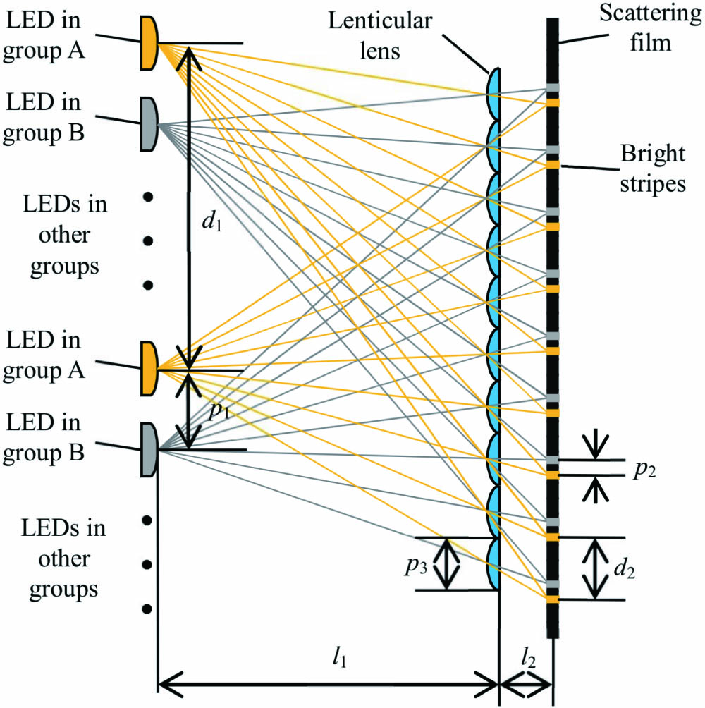
As shown in Fig. 1, the micro-projection dynamic backlight is composed of a light emitting diodes (LEDs) array, a lenticular lens array, and a scattering film. The LED array, the lenticular lens, and the scattering film construct a micro-projection structure. The LEDs in the array are divided into several groups. The light from each LED group can be projected to the scattering film by the lenticular lens and forms a series of bright stripes. The LEDs in each group have a calculated pitch, so the bright stripes formed by these LEDs will coincide precisely. The different LED groups have different horizontal positions, so these bright stripes corresponding to different LED groups also have different horizontal positions. Therefore, dynamically lighting different LED groups can form a dynamic backlight.
![]()
Figure 1.Structure of the proposed micro-projection dynamic backlight.
Suppose that the distance between the LEDs and the lenticular lens is
Sign up for Chinese Optics Letters TOC. Get the latest issue of Chinese Optics Letters delivered right to you!Sign up now
According to the above geometric relationships, more optional bright stripes can be provided in a period
As shown in Fig. 2, each LED will form an image on the scattering layer through a lenticular lens unit. Suppose that the focal length of the lenticular lens unit is
![]()
Figure 2.Imaging process of the LEDs.
Because the distance between the LEDs array and the lenticular lens
The bright stripes constrained by Eqs. (3) and (5) can be used for multi-view 3D display. Figure 3 shows a recommended multi-view 3D display based on the proposed micro-projection dynamic backlight. The structure of the recommended multi-view 3D display consists of a proposed backlight, a lenticular lens, and a transparent LCD panel. As we discussed before, the LED groups of the micro-projection dynamic backlight can provide a series of bright stripes on the scattering film. These bright stripes can provide light energy for display. The lenticular lens can project the light from the bright stripes into views, and the transparent LCD panel can provide parallax images. Furthermore, the scattering coefficient of the transparent LCD panel is very low, so it will not influence the light transmission.
![]()
Figure 3.Multi-view 3D display based on the proposed micro-projection dynamic backlight.
The light from the bright stripes for an LED group can be projected by the lenticular lens and concentrated into a viewpoint. Simultaneously, the transparent LCD panel shows the corresponding parallax image. Then, this parallax image can be observed at the viewpoint. Therefore, multi-view 3D display can be achieved by lighting the LED groups and providing the corresponding parallax image.
Suppose that the distance between the scattering film and the lenticular lens is
Therefore, firstly, because the proposed micro-projection dynamic backlight can provide bright stripes with a small pitch of
3. Experimental Results
The prototype is shown in Fig. 4. The flat display panel is used to simulate the LEDs array. Eight groups of bright stripes can be displayed on the flat display panel to simulate the LEDs array. The scattering film is made of polyethylene terephthalate (PET) diffusion film with a thickness of 0.125 mm. On the scattering film, a lenticular lens and a transparent LCD panel are placed in turn. The parameters of the prototype are shown in Table 1.
| Section | Parameters | Value |
|---|---|---|
| Backlight | Pitch of lenticular lens array | 0.99 mm |
| Backlight | Distance between the LEDs array and lenticular lens array | 58.99 mm |
| Backlight | Distance between the lenticular lens and the scattering film | 4.866 mm |
| Backlight | Distance between the LEDs in the same group | 20.26 mm |
| Backlight | Distance between the formed bright stripes | 0.13 mm |
| Backlight | Distance between the adjacent LED groups | 2.53 mm |
| Backlight | Pitch between the formed stripes corresponding to the adjacent LED groups | 0.049 mm |
| Backlight | Width of the LED | 0.95 mm |
| Display | Pitch of lenticular lens array | 1.05 mm |
| Display | Distance between the lenticular lens and the scattering film | 3.774 mm |
| Display | Pupil distance | 65 mm |
| Display | Optimal viewing distance | 1200 mm |
| Display | Size of transparent LCD panel | 21 inch |
Table 1. Parameters of the Prototype
![]()
Figure 4.Experimental setup.
The lenticular lens array used in the experiment can realize 12 viewpoints theoretically, but only an eight-viewpoint prototype is developed due to the aberration of the lenticular lens array. If the lenticular lens array with larger pitch and smaller aberration is produced, the number of viewpoints can be further increased.
According to the above parameters, the LEDs array with a pitch of 2.53 mm and a width of 0.95 mm will form bright stripes with a pitch of 0.13 mm and a width of 0.049 mm on the scattering film. Matching the lenticular lens array, the prototype can form eight viewpoints. However, if LED chips are directly used to project light without the lenticular lens array in the backlight, only one viewpoint can be formed.
In order to verify the display effect of the 3D display, the images of numbers from “1” to “8” are used in the experiment, as shown in Fig. 5. The images of eight numbers are provided by the transparent LCD panel at eight moments, respectively, and are projected into eight different viewpoints. The display effect is shown in Fig. 6, the pictures of Figs. 6(a), 6(c), 6(e) to 6(o) are taken on the viewpoints, and the others are taken on the non-viewpoint, which is 65 mm to the left of the viewpoints. The experimental results show that the 3D display can complete a multi-view 3D display with full resolution correctly. The experimental results show that there is some crosstalk. The crosstalk is mainly caused by the following reasons: (1) the width of the bright stripe on the scattering film is larger than the theoretical value due to the aberration of the lenticular lens; (2) there is light scattering when the light passes through the optical elements; (3) there is reflected light on the surface of the optical elements, which will emit again after many times of reflection.
![]()
Figure 5.Images of numbers from 1 to 8.
![]()
Figure 6.Pictures captured at viewpoints and non-viewpoints.
The optical simulation is also carried out, and the light distribution is simulated by using ASAP software, as shown in Fig. 7. In the simulation, the ISO light source in ASAP was used, and the divergence angle was set to 120 deg. The simulation results show that the 3D display can complete the correct projection of the parallax image.
![]()
Figure 7.Luminance distribution of the developed prototype.
Finally, two actual parallax images are selected to verify the display effect in adjacent views in the experiment. The adopted parallax images are shown in Fig. 8(a), and the display effect is shown in Fig. 8(b). The experimental results show that the full resolution parallax image can be correctly projected to the corresponding viewpoint to form a 3D image.
![]()
Figure 8.Pictures captured at optimal viewing distance.
Experimental results show that there is a certain color difference, because the LCD display has directional characteristics, such as vertical alignment (VA) technology. The normal LCD displays use uniform backlighting, but in this experiment directional backlighting was used. The LCD panel suitable for directional backlighting can be made to eliminate color difference.
In addition, the experimental results show that the brightness distribution is non-uniform, because the micro-projection structure provides linear backlighting, which leads to the non-uniform distribution of brightness. A gradient transmittance mask, of which transmittance of the central area is lower than that of the two sides, can be added to the LED to improve brightness uniformity.
4. Conclusions
A micro-projection dynamic backlight for multi-view 3D display is proposed. The proposed backlight includes an LEDs array, a lenticular lens array, and a scattering film. The LED array, the lenticular lens, and the scattering film construct a micro-projection structure. The light emitting from the LEDs of the backlight converges through the lenticular lens array and forms a series of bright stripes on the scattering film. These bright stripes can provide light energy for 3D display based on the lenticular lens array. The lenticular lens can project the light from the bright stripes into views, and the transparent LCD panel can provide parallax images. An eight-viewpoint 3D display prototype based on the proposed backlight is developed. The experimental results show that the proposed backlight can correctly project the full parallax image to the corresponding viewpoint. The backlight can match any LCD panel to complete a multi-view 3D display with full resolution.
References
[1] B. Javidi, F. Okano. Three-Dimensional Television, Video, and Display Technologies(2002).
[2] H. Urey, E. Erden. State of the art in stereoscopic and autostereoscopic displays. Proc. IEEE, 99, 540(2011).
[3] G. J. Lv, J. Wang, W. X. Zhao, Q. H. Wang. Three-dimensional display based on dual parallax barriers with uniform resolution. Appl. Opt., 52, 6011(2013).
[4] J. Geng. Three-dimensional display technologies. Adv. Opt. Photon., 5, 456(2013).
[5] F. Wu, H. Deng, C. G. Luo, D.-H. Li, Q. H. Wang. Dual-view integral imaging three-dimensional display. Appl. Opt., 52, 4911(2013).
[6] Q. H. Wang, C. C. Ji, L. Li, H. Deng. A dual-view integral imaging 3D display by using orthogonal polarizer array and polarization switcher. Opt. Express, 24, 9(2016).
[7] Q. G. Ma, L. C. Cao, Z. H. He, S. D. Zhang. Progress of three-dimensional light-field display [invited]. Chin. Opt. Lett., 17, 111001(2019).
[8] X. X. Xia, X. Liu, H. F. Li, Z. Zheng, H. Wang, Y. Peng, W. Shen. A 360-degree floating 3D display based on light field regeneration. Opt. Express, 21, 11237(2013).
[9] P. A. Blanche, A. Bablumian, R. Voorakaranam, C. Christenson, W. Lin, T. Gu, D. Flores, P. Wang, W.-Y. Hsieh, M. Kathaperumal, B. Rachwal, O. Siddiqui, J. Thomas, R. A. Norwood, M. Yamamoto, N. Peyghambarian. Holographic three-dimensional telepresence using large-area photorefractive polymer. Nature, 468, 80(2010).
[10] F. C. Fan, S. Choi, C. C. Jiang. Demonstration of full-parallax three-dimensional holographic display on commercial 4 K flat-panel displayer. Chin. Opt. Lett., 14, 010007(2016).
[11] Q. H. Wang. 3D Display Technology and Device(2011).
[12] Q. H. Wang, Y. H. Tao, W. X. Zhao, D. Li. A full resolution autostereoscopic 3D display based on polarizer parallax barrier. Chin. Opt. Lett., 8, 010022(2010).
[13] J. C. Liou, F.-H. Chen. A novel time-multiplexed autostereoscopic multiview full resolution 3D display. Proc. SPIE, 8288, 82880U(2012).
[14] J. C. Schultz, R. Brott, M. Sykora, W. Bryan, T. Fukamib, K. Nakao, A. Takimoto. 11.5L: late-news paper: full resolution autostereoscopic 3D display for mobile applications. Sid Symp. Digest Tech. Papers, 40, 127(2012).
[15] J. L. Feng, Y. J. Wang, S. Y. Liu, D.-C. Hu, J.-G. Lu. Three-dimensional display with directional beam splitter array. Opt. Express, 25, 1564(2017).
[16] H. J. Lee, H. Nam, J. D. Lee, H. W. Jang, M. S. Sung, B. S. Kim, J. S. Gu, C. Y. Park, K. H. Choi. 8.2: a high resolution autostereoscopic display employing a time division parallax barrier. SID Symp. Digest Tech. Papers, 37, 81(2012).


Set citation alerts for the article
Please enter your email address

© Copyright 2018-2021 | Chinese Laser Press. All Rights Reserved 沪ICP备15018463号-20