1State Key Laboratory of Optoelectronic Materials and Technologies, School of Electronics and Information Technology, Sun Yat-sen University, Guangzhou 510275, China
2Photonics Group, Merchant Venturers School of Engineering, University of Bristol, Bristol BS8 1UB, UK
Light fields with extraordinary propagation behaviors, such as nondiffracting and self-bending, are useful in the optical delivery of energy, information, and even objects. A kind of helical beam is constructed here based on the caustic method. With the appropriate design, the main lobe of these helical beams can be both well-confined and almost nondiffracting, while moving along a helix with its radius, period, number of rotations, and main lobes highly adjustable. In addition, the peak intensity of the main lobe fluctuates below 15% during propagation. These promising characteristics may enable a variety of potential applications based on these beams.
Accelerating beams are light fields capable of self-bending in free space without any external potential. Such beams have gained great attention, not only for their counterintuitive propagation behavior, but also for the promising versatile applications in the delivery of energy, information, and even objects, or guiding, using light that ranges from micro-machining[1], imaging[2,3], and particle manipulation[4,5] to laser-assisted guiding of particular processes like electric discharge[6] and plasma generation[7].
The first accelerating beam was demonstrated in 2007, where a light field with an initial Airy distribution is found to propagate along a parabolic trajectory[8,9]. Since then, considerable research has been carried out to construct other kinds of accelerating beams propagating along various trajectories[10–13]. Among these, the helical trajectory is of particular interest for its remarkable rotating behavior, as well as the potential relationship with optical vortices[14–17]. The construction of helical beams at present mainly falls into two categories. One scheme is to superpose different order Bessel or Laguerre–Gaussian beams[18–23]. This does allow for great freedom in the construction of helical beams with a variety of transverse profiles, but it is unable to ensure a satisfying main lobe like a well-confined hot spot to be constructed. Another scheme is to impose a spiral-shaped phase or amplitude modulation[16,24–26], as well as the helico-conical phase[17,27,28] to the incident beam. However, although there is a clear main lobe where these beams propagate along helical trajectories, the characteristics of the main lobe are mostly lack of discussion, which is actually necessary and significant for practical applications.
In this work, a kind of helical beam is constructed based on the caustic method, whose main lobes move exactly along helical trajectories. The angular spectrum of this kind of beams is found to be conjugated with one of the helico-conical beams previously proposed[27], which suggests that the helical propagation behaviors of the helico-conical beam before the focus is easy to explain. In order to improve the quality of the main lobe during the helical propagation, an additional ring-shaped amplitude modulation is introduced, which allows the main lobe to be well-confined and almost nondiffracting at the same time. The helical beam is highly adjustable, including the radius and period of the helix, as well as the number of rotations and main lobes. In addition, other characterizations of the main lobe are also given, in which the promising characteristics presented are attractive and desirable for considerable applications.
Sign up for Chinese Optics Letters TOC. Get the latest issue of Chinese Optics Letters delivered right to you!Sign up now
Note that the propagation of a scalar light field in a linear isotropic medium can be described by an angular spectrum integral, where is the field distribution at the space point , while and are the amplitude and phase of the angular spectrum in the initial plane, with and as the spatial frequency along the - and -axes, respectively. Furthermore, under the paraxial approximation, the spatial frequency along the propagating direction can be expressed in the form of with as the wave number in the linear medium, which is the case discussed in this Letter. The wavelength of the light beam and the refractive index of the medium are 632.8 nm and 1.5, respectively.
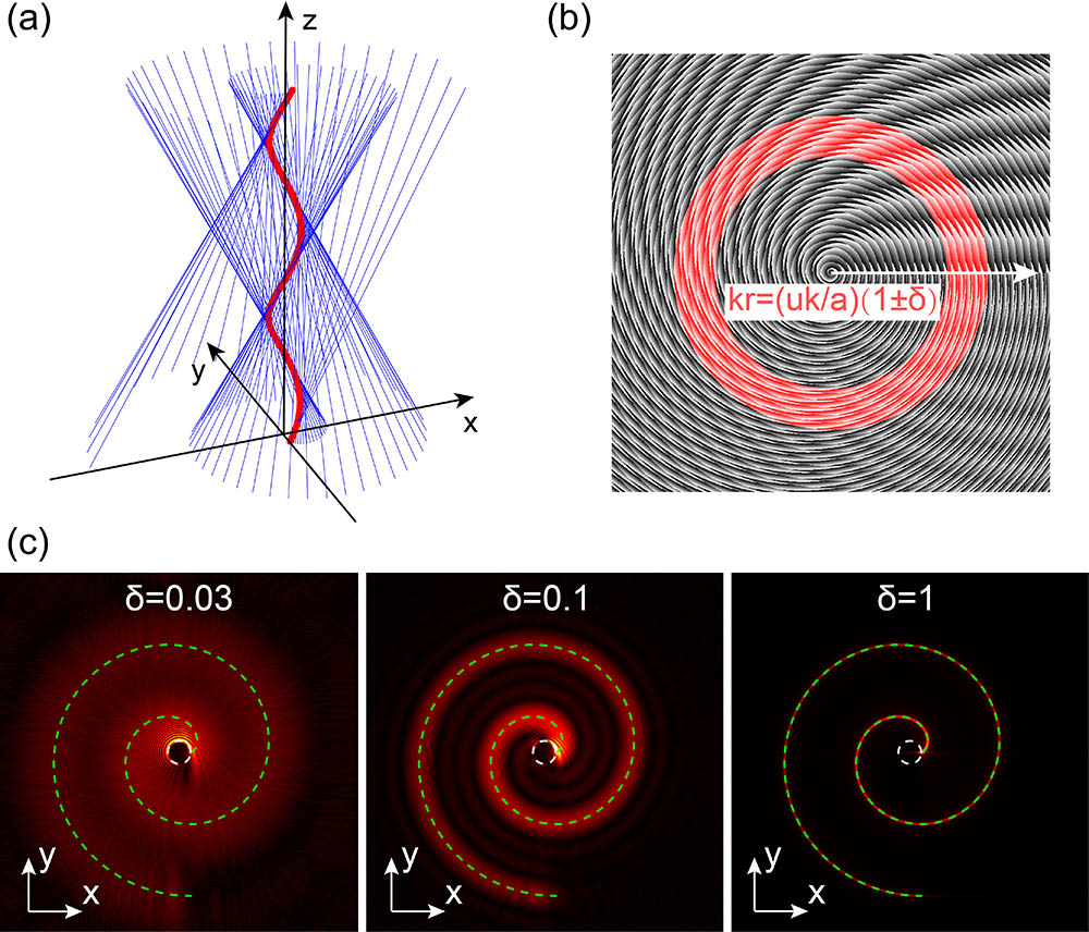
With an appropriate design of the angular spectrum, a variety of light fields could be obtained based on Eq. (1), including the helical beams to be constructed, while the angular spectrum in the initial plane is required as the initial parameter. In order to determine the initial angular spectrum needed, we employ the caustic method to construct the helical beams, which associates the desired trajectory with an optical caustic, the envelope of a bundle of light rays[29]. In this case, the helical trajectory can be expressed mathematically by a parametric equation, where is the parameter, is the radius, and is the period, as shown in Fig. 1(a) by a red curve. The light ray in blue tangential to this trajectory can be described by its tangential equation which intersects the initial plane at the point in the direction (or at a spatial frequency) or expressed in the polar coordinate as
Figure 1.Design of the helical beams. (a) Superposition of light rays in blue to form a helical caustic in red. (b) Angular spectrum of the helical beam in the initial plane with the phase distribution in grayscale, and an additional ring-shaped amplitude distribution in red with a spatial frequency width described by . (c) The initial field distribution corresponding to different spatial frequency widths .
Note that the coordinate in the initial plane is denoted as for simplicity. By applying the stationary phase approximation to Eq. (1) in the initial plane, we can obtain which actually can be explained as a mean approximation in the perspective of the Wigner distribution[13,30]. Furthermore, by employing the chain rule between the polar coordinates and the rectangular coordinates, the derivatives of phase function in the polar coordinate system are which result in an analytical form of the phase function as
This result is interesting because the radial and azimuthal dependence is inseparable, which reminds the helico-conical beams proposed in Ref. [27] to be straightforward in the form of In the case of , the phase function in Eq. (12) has almost the same form as Eq. (11), except for the minus, which leads to the helical propagation of the main lobe observed before the focus rather than after the focus as in Ref. [27]. Therefore, a clear explanation is given here for the helico-conical beams in the case of , regarding the characteristics of the spiral shapes [described by Eq. (4)] and the helical propagation behavior [described by Eq. (2)] based on our caustic analysis above.
The phase distribution of the angular spectrum described by Eq. (11) is presented in Fig. 1(b) with a grayscale for a designed two-rotation helical beam. On the other hand, it is noted that the radial spatial frequency is constant according to Eq. (6), indicating that the amplitude distribution of the angular spectrum is a delta function and results in degeneration to a Bessel beam. To avoid this, a ring-shaped amplitude distribution with a certain width is introduced instead, as shown in red in Fig. 1(b), where is defined as the percentage of the half width over the central spatial frequency . Varying the spatial frequency width , the corresponding field distributions in the initial plane are presented in Fig. 1(c). As can be seen, when is small, the initial field distribution tends to form a ring-like Bessel beam. As increases, the amplitude distribution evolves into a spiral shape with a clear main lobe, which is fitted precisely by Eq. (4) under the caustic analysis.
With the above angular spectra in the initial plane, the propagation dynamics of these beams can be obtained by taking the numerical calculation of Eq. (1). The simulation results are shown in Fig. 2, corresponding to each initial field distribution that is shown in Fig. 1(c). Basically, the spatial frequency spectrum extending to a width has two effects on the beam. On one hand, the main lobe is better confined with a larger , due to more spatial frequency components participating in the interference cancellation, and thus leading to a better confinement in space. While on the other hand, as increases, the main lobe spreads out more quickly, because of that each radial spatial frequency actually corresponds to a different period of the helix, according to Eq. (6). When the width is larger, the out-of-sync situation becomes worse. This is clearly shown in Fig. 2(c), where the main lobe spreads out quickly, and then the faster components catch up with the slower components, leading to the subsequent interference phenomenon. Therefore, the selection of width needs to balance both the confinement and the spreading of the main lobe. With an appropriate width , a better helical propagation behavior can be obtained, as shown in Fig. 2(b), where the main lobe is well-confined and almost propagates along a helical trajectory of 20 μm in the radius and 2000 μm in the period as designed. However, it is also noted that the main lobe deteriorates near the beginning and end of the predesigned caustic trajectory, owing to fewer spatial frequency components participating in the interference there.
Figure 2.Cross-sectional intensity distribution of helical beams with spatial frequency width set to be (a) 0.03, (b) 0.1, and (c) 1, corresponding to Fig. 1(c). The radius and period of the predesigned helical trajectory are 20 and 2000 μm, respectively.
In order to improve the quality of the main lobe during the propagation along the desired trajectory, more spatial frequency components are included apart from those essential to the desired caustic. With this improvement, the main lobe becomes much better, especially at the beginning and end of the required trajectory, as shown in Fig. 3(a). Moreover, the period of the helix is obtained clearly in this case, which is about 2018 μm, within the uncertain range of (2000/1.1,2000/0.9) μm due to the extension of the spatial frequency spectrum, and the period can actually be adjusted at will by simply altering the central spatial frequency. In addition to the radius, period, and number of rotations of the helix capable of tailoring freely in the previous caustic analysis, it is found that the number of main lobes is also adjustable. For this demonstration, we have constructed helical beams with the number of main lobes varying from one to four, as shown in Fig. 3, based on the abovementioned helical beam. The propagation dynamics of these helical beams is attractive and desirable since all of the main lobes are well-confined and almost nondiffracting during propagation, which has potential applications for micro-manipulation, for instance, to trap a different number of particles at the same time. Although the period of the helix is slightly different, it can be easily compensated by shifting the central spatial frequency as mentioned before.
Figure 3.Propagation dynamics of helical beams with different numbers of main lobes. The helical beams presented include (a) one-lobe, (b) two-lobe, (c) three-lobe, and (d) four-lobe with slightly different periods of 2018, 1970, 1917, and 2087 μm, respectively.
It is noted that the most important and common characterizations of such helical beams include the percentage of the power contained in the main lobe and the fluctuation of the peak intensity during propagation. Here, the percentage of the power within a circle in the radius of is calculated and presented in Fig. 4(a) for the constructed helical beams in Fig. 3. When is small, there is almost no optical power in the dark center. As increases and crosses the main lobe, the power rises quickly and then remains flat again after passing the main lobe. The variation is fitted well with an error function, which indicates a nice Gaussian intensity distribution of the main lobe along the radial direction, with an FWHM to be around 3.8 μm. From the fitted results, we find that the percentage of the power contained in the main lobe for these helical beams with one to four lobes is 6.6%, 6.6%, 6.8%, and 6.4%, respectively, which is related to the number of rotations and the amount of additional spatial frequency as designed. Moreover, the fluctuation of the peak intensity during propagation is within 15% (mostly within 10%) and might be further improved with optimization.
Figure 4.Characterization of the helical beams with different numbers of main lobes in Fig. 3. (a) The percentage of power within a circle in the radius of , which is fitted by , , , and for helical beams with one to four main lobes, respectively. Note that the curves for two-lobe, three-lobe, and four-lobe helical beams are shifted upward by 0.01, 0.02, and 0.03 for better visualization. The inset shows the first two flat states in the curve and contains the main lobe. (b) The fluctuation of the peak intensity during the two-rotation helical propagation, which is normalized by the initial peak intensity for a better comparison.
In conclusion, we construct a kind of helical beam based on the caustic method with an additional ring-shaped amplitude distribution. This kind of beam is related to one of the helico-conical beams, and thus clearly explains its helical propagation behavior before the focus. With an appropriate design, the main lobe of these helical beams can be both well confined and almost nondiffracting, while moving along a predesigned helical trajectory with its radius, period, and number of rotations highly adjustable. In addition, there are promising characteristics of these helical beams, including the adjustable number of main lobes, around 6.6% of the power contained in the main lobe related to specific design, and the fluctuation of the peak intensity below 15%, which makes them attractive for a variety of applications ranging from micro-machining and imaging to micro-manipulation and laser-assisted guiding.