• Acta Photonica Sinica
  • Vol. 49, Issue 7, 712004 (2020)
Hao WEN, Zhao-zong MENG, Nan GAO*, and Zong-hua ZHANG
Author Affiliations
  • School of Mechanical Engineering, Hebei University of Technology, Tianjin 300130, China
  • show less
    DOI: 10.3788/gzxb20204907.0712004 Cite this Article
    Hao WEN, Zhao-zong MENG, Nan GAO, Zong-hua ZHANG. Error Measurement and Compensation of Multi-channel Fringe Projection System[J]. Acta Photonica Sinica, 2020, 49(7): 712004 Copy Citation Text show less
    Multi-channel 3D measurement principle process
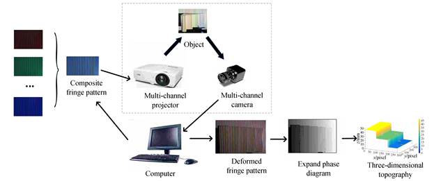
    Fig. 1. Multi-channel 3D measurement principle process
    Schematic diagram of folded phase
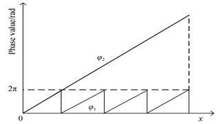
    Fig. 2. Schematic diagram of folded phase
    Multi-channel 3D measurement system structure
    Fig. 3. Multi-channel 3D measurement system structure
    Schematic diagram of the error relation of the collected light intensity
    Fig. 4. Schematic diagram of the error relation of the collected light intensity
    Construction process diagram of the position deviation relation
    Fig. 5. Construction process diagram of the position deviation relation
    Matching pixels
    Fig. 6. Matching pixels
    System error compensation method
    Fig. 7. System error compensation method
    Experimental system
    Fig. 8. Experimental system
    Intensity distribution of each color channel in a single-color fringe image
    Fig. 9. Intensity distribution of each color channel in a single-color fringe image
    Pixel deviation distribution of red and green fringe image
    Fig. 10. Pixel deviation distribution of red and green fringe image
    Phase difference distribution of a row in the red and green vertical fringe image
    Fig. 11. Phase difference distribution of a row in the red and green vertical fringe image
    Unwrapped phase distribution of a row in a color fringe image
    Fig. 12. Unwrapped phase distribution of a row in a color fringe image
    3D topography measured by the color fringe projection system
    Fig. 13. 3D topography measured by the color fringe projection system
    Step distanceStandard valueBefore compensationAfter compensationError before compensationError after compensation
    1 and 217.60217.00517.636-0.5970.034
    2 and 318.42219.13518.4350.7130.013
    3 and 413.25813.98213.2130.724-0.045
    Table 1. Measurement accuracy of step before and after compensation (unit: mm)
    Hao WEN, Zhao-zong MENG, Nan GAO, Zong-hua ZHANG. Error Measurement and Compensation of Multi-channel Fringe Projection System[J]. Acta Photonica Sinica, 2020, 49(7): 712004
    Download Citation