
Qiubai Yang, Yan Jiao, Chunlei Yu, Chongyun Shao, Fengguang Lou, Shikai Wang, Lei Zhang, Qiuhong Yang, Lili Hu, "Gain and laser performance of heavily Er-doped silica fiber fabricated by MCVD combined with the sol-gel method," Chin. Opt. Lett. 19, 110603 (2021)
- Chinese Optics Letters
- Vol. 19, Issue 11, 110603 (2021)
Abstract
1. Introduction
Since the 90s, Er-doped fiber amplifiers (EDFAs) play an important role in modern optical telecommunications. Besides this, in recent years, high-repetition-rate (HRR) or single-frequency (SF) Er-doped fiber lasers (EDFLs) are widely applied in some specific fields, owing to their eye safety and high atmospheric transmission, such as remote sensing, LIDAR, and gravitational wave detection[
However, for silica-based EDFs manufactured by modified chemical vapor deposition (MCVD), the doping concentration is limited by
Several researchers focus on non-silica fibers[
Sign up for Chinese Optics Letters TOC. Get the latest issue of Chinese Optics Letters delivered right to you!Sign up now
Several fiber manufacturing processes based on the CVD process have been developed to ensure uniform dispersion of Er ions, such as surface plasma chemical vapor deposition (SPCVD)[
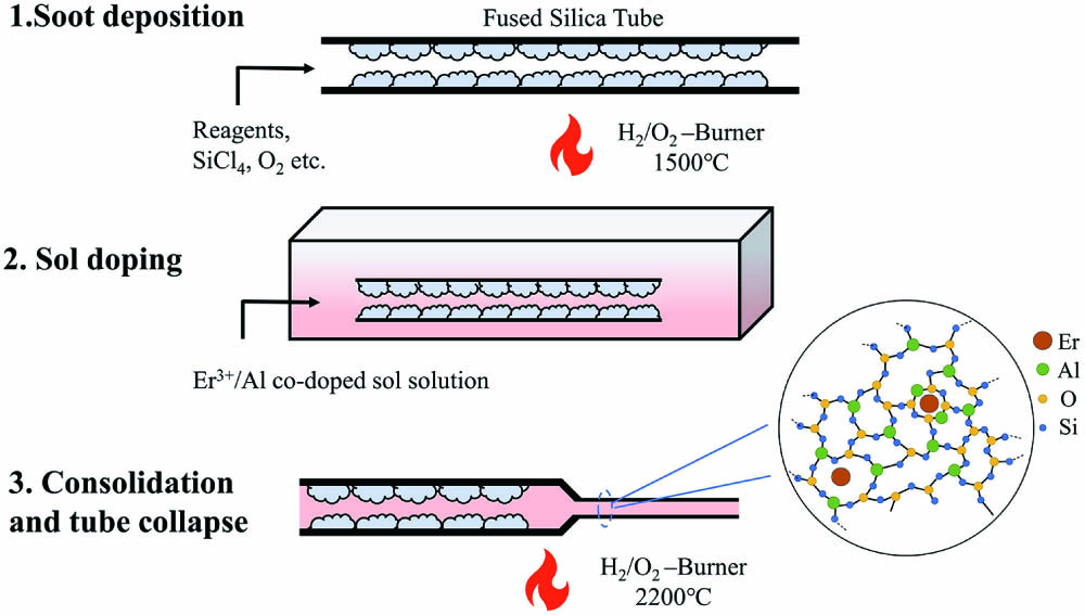
In this Letter, we introduced an MCVD combined with sol doping technology to fabricate heavily doping silica fiber. This fiber fabrication method combines the advantage of low-loss preparation of MCVD and the sol-gel merit of high doping homogeneity. Based on this technique, we prepared a heavily Er-doped silica fiber (MCVD and SG-EDF, MS-EDF). The core absorption and background loss were measured using the cut-back method. The unsaturable absorptions of the MS-EDF and the SG-EDF were measured to estimate the CIQ effect. Also, gain and short-cavity lasing properties of the MS-EDF were invested and discussed in all-fiber schemes.
2. Fiber Fabrication
The method of preparing the
![]()
Figure 1.Schematic diagram of fiber preform fabrication.
Figure 2(a) shows the radial refractive index profile (RIP) measured by an optical fiber analyzer (IFA-100). It is shown that there is no central dip in the RIP, and the refractive index fluctuation is lower than
![]()
Figure 2.(a) Radial refractive index profile. Inset: micrograph of MS-EDF cross section. (b) Concentrations of Al3+ and Er3+ in the MS-EDF and SG-EDF from EPMA measurement.
The core background loss and absorption spectra were measured with a white light source and an optical spectrum analyzer (OSA) by the cut-back method. In Fig. 3(a), we plotted the background loss spectra of the heavily EDF. The background loss is about 20 dB/km at 1100 nm, which is much lower than the 200 dB/km of the SG-EDF reported in Ref. [21], owing to the low-loss MCVD fabrication process. The core absorption spectrum was measured using a short fiber, and the result was plotted in Fig. 3(b). The core absorption coefficients of the MS-EDF at 980 nm and 1530 nm were about 65 dB/m and 128 dB/m, respectively.
![]()
Figure 3.(a) Background loss and (b) absorption of the MS-EDF.
3. Experiments and Results
The lifetime of the metastable level in the clustered
![]()
Figure 4.(a) Simplified energy level diagram of isolated Er3+ ions and Er3+-Er3+ pairs with an excitation at 980 nm. (b) Unsaturable absorptions at 976 nm of a 25 cm SG-EDF (blue) and a 32 cm MS-EDF (red). (c) Fluorescence decay curves obtained from the two fibers.
The unsaturable absorptions of the MS-EDF and the SG-EDF at 976 nm are shown in Fig. 4(b). The lengths of two fibers were chosen for providing the same absorption of pump power at 976 nm, and it can be seen in Fig. 4(b) that the maximum small-signal absorptions of two fibers are both about 22 dB. With the input laser power increasing, the absorption was decreased rapidly and became stable gradually. The stable value is called unsaturable absorption, and the unsaturable absorption fraction is the ratio of unsaturable absorption to the maximum absorption. This part of absorbed pump power cannot transfer to laser power, and thus it can be considered as “excess background loss” to a certain extent. When the injected pump power is 199 mW, the absorption of the MS-EDF is 9.3 dB, thus the unsaturable absorption fraction is
We also measured the fluorescence decay of the
As is shown in Fig. 5(a), the gain properties of the MS-EDF were evaluated with an all-fiber EDFA setup. The EDFA was seeded by a tunable light source (TSL) operated in the C + L band. An optical isolator (ISO) was placed after the seed source to protect the TSL from backward propagating light. The signal optical power injected into the EDFA was fixed to be
![]()
Figure 5.(a) Schematic of EDFA experiment. (b) Dependence of the gain and NF of the MS-EDF on the wavelength with different fiber lengths.
Figure 5(b) shows the signal gain and NF from 1520 to 1600 nm under 500 mW launched pump power and
The short-cavity laser performance was investigated, employing a short linear cavity scheme as in Fig. 6(a). A laser cavity was formed by a pair of fiber Bragg gratings (FBGs) fabricated in a standard 1.5 µm single-mode fiber (SMF-28e, Corning). The reflectivity of the low-reflectivity (LR) FBG is
![]()
Figure 6.(a) Schematic of short-cavity laser experiment. (b) Dependence of laser output power on absorption pump power for different fiber length. (c) Laser spectra of 3.7 and 1.8-cm-long fibers. Inset: the enlarged and normalized spectrum (left) and the picture of the laser cavity (right) using the 3.7-cm-long MS-EDF.
The dependence of laser output power on absorbed pump power for five different fiber lengths (3.7, 5.0, 5.7, 6.5, and 8.0 cm) is illustrated in Fig. 6(b). With the increased fiber length, the slope efficiency initially increases from 13.6% to 20.4%, then decreases from 20.4% to 13.6%. The highest slope efficiency of 20.4% and output power of 11.9 mW were obtained in a 6.5-cm-long MS-EDF under 81 mW absorbed pump power. The slope efficiency of 20.4% is higher than the value reported for SG-EDF (12%, in Ref. [31]), and it can be attributed to lower background loss.
For a longer fiber, the signal power was reabsorbed by an extra active fiber, which results in lower laser efficiency. For a shorter length fiber, it is very difficult to absorb enough pump power and provide enough gain, resulting a larger threshold and lower slope efficiency. The output spectra of a 3.7 cm and a 1.8 cm MS-EDF are shown in Fig. 6(c), and the left inset is the enlarged and normalized laser spectrum, which was measured at a resolution of 0.02 nm. The laser spectrum of the 3.7 cm MS-EDF was centered at 1533.7 nm with a 0.014 nm spectrum linewidth full width at half-maximum (FWHM), and it shows great optical signal-to-noise ratio (OSNR) performance. Meanwhile, it can be noted that the 1.8-cm-long MS-EDF could not achieve effective lasing due to insufficient gain, although we maximized the pump power.
4. Conclusion
In this Letter, we proposed a technique to fabricate heavily EDFs combining commercial MCVD with the sol-gel method. The proposed technique can achieve a uniform dispersion of Er ions in a silica matrix, and the clustered
References
[1] C. C. V. Philippov, Y. Jeong, C. Alegria, J. K. Sahu, J. Nilsson. High-energy in-fiber pulse amplification for coherent lidar applications. Opt. Lett., 29, 2590(2004).
[2] W. Lee, J. Geng, S. Jiang, A. W. Yu. 1.8 mJ, 3.5 kW single-frequency optical pulses at 1572 nm generated from an all-fiber MOPA system. Opt. Lett., 43, 2264(2018).
[3] C. Lei, H. Feng, Y. Messaddeq, S. LaRochelle. Investigation of C-band pumping for extended L-band EDFAs. J. Opt. Soc. Am. B, 37, 2345(2020).
[4] J. L. Y. Liu, W. Chen. Eye-safe, single-frequency pulsed all-fiber laser for Doppler wind lidar. Chin. Opt. Lett., 9, 090604(2011).
[5] S. Han, H. Jang, S. Kim, Y.-J. Kim, S.-W. Kim. MW peak power Er/Yb-doped fiber femtosecond laser amplifier at 1.5 µm center wavelength. Laser Phys. Lett., 14, 080002(2017).
[6] V. Kuhn, D. Kracht, J. Neumann, P. Weßels. Er-doped single-frequency photonic crystal fiber amplifier with 70 W of output power for gravitational wave detection. Proc. SPIE, 8237, 82371G(2012).
[7] O. Varona, M. Steinke, J. Neumann, D. Kracht. All-fiber, single-frequency, and single-mode Er3+:Yb3+ fiber amplifier at 1556 nm core-pumped at 1018 nm. Opt. Lett., 43, 2632(2018).
[8] M. M. Khudyakov, D. S. Lipatov, A. N. Gur’yanov, M. M. Bubnov, M. E. Likhachev. Highly efficient 3.7 kW peak-power single-frequency combined Er/Er-Yb fiber amplifier. Opt. Lett., 45, 1782(2020).
[9] Z. Guo, Q. Hao, J. Peng, H. Zeng. Environmentally stable Er-fiber mode-locked pulse generation and amplification by spectrally filtered and phase-biased nonlinear amplifying long-loop mirror. High Power Laser Sci. Eng., 7, e47(2019).
[10] J. Bogusławski, G. Soboń, R. Zybała, J. Sotor. Towards an optimum saturable absorber for the multi-gigahertz harmonic mode locking of fiber lasers. Photon. Res., 7, 1094(2019).
[11] X. Chen, Y. Gao, J. Jiang, M. Liu, A. Luo, Z. Luo, W. Xu. High-repetition-rate pulsed fiber laser based on virtually imaged phased array. Chin. Opt. Lett., 18, 071403(2020).
[12] A. Martinez, S. Yamashita. Multi-gigahertz repetition rate passively modelocked fiber lasers using carbon nanotubes. Opt. Express, 19, 6155(2011).
[13] A. M. Smirnov, A. P. Bazakutsa, Y. K. Chamorovskiy, I. A. Nechepurenko, A. V. Dorofeenko, O. V. Butov. Thermal switching of lasing regimes in heavily doped Er3+ fiber lasers. ACS Photon., 5, 5038(2018).
[14] S. H. Xu, Z. M. Yang, T. Liu, W. N. Zhang, Z. M. Feng, Q. Y. Zhang, Z. H. Jiang. An efficient compact 300 mW narrow-linewidth single frequency fiber laser at 1.5 µm. Opt. Express, 18, 1249(2010).
[15] N. Boetti, D. Pugliese, E. Ceci-Ginistrelli, J. Lousteau, D. Janner, D. Milanese. Highly doped phosphate glass fibers for compact lasers and amplifiers: a review. Appl. Sci., 7, 1295(2017).
[16] X. Gao, Z. Zhao, Z. Cong, G. Gao, A. Zhang, H. Guo, G. Yao, Z. Liu. Stable 5-GHz fundamental repetition rate passively SESAM mode-locked Er-doped silica fiber lasers. Opt. Express, 29, 9021(2021).
[17] B. J. Ainslie. A review of the fabrication and properties of erbium-doped fibers for optical amplifiers. J. Lightwave Technol., 9, 220(1991).
[18] E. Maurice, G. Monnom, B. Dussardier, D. B. Ostrowsky. Clustering-induced nonsaturable absorption phenomenon in heavily erbium-doped silica fibers. Opt. Lett., 20, 2487(1995).
[19] D. Boivin, T. Föhn, E. Burov, A. Pastouret, C. Gonnet, O. Cavani, C. Collet, S. Lempereur. Quenching investigation on new erbium doped fibers using MCVD nanoparticle doping process. Proc. SPIE, 7580, 75802B(2010).
[20] P. G. Rojas Hernandez, M. Belal, C. Baker, S. Pidishety, Y. Feng, E. J. Friebele, L. B. Shaw, D. Rhonehouse, J. Sanghera, J. Nilsson. Efficient extraction of high pulse energy from partly quenched highly Er3+-doped fiber amplifiers. Opt. Express, 28, 17124(2020).
[21] A. Dhar, A. Pal, M. C. Paula, P. Ray, H. S. Maiti, R. Sen. The mechanism of rare earth incorporation in solution doping process. Opt. Express, 16, 12835(2008).
[22] Y. Jiao, M. Guo, R. Wang, C. Shao, L. Hu. Influence of Al/Er ratio on the optical properties and structures of Er3+/Al3+ co-doped silica glasses. J. Appl. Phys., 129, 053104(2021).
[23] C. Yang, X. Guan, W. Lin, Q. Zhao, G. Tang, J. Gan, Q. Qian, Z. Feng, Z. Yang, S. Xu. Efficient 1.6 µm linearly-polarized single-frequency phosphate glass fiber laser. Opt. Express, 25, 29078(2017).
[24] K. Linganna, J.-H. In, J.-T. Ahn, Y. Choi, Y.-E. Im, D.-B. Kim, J. H. Choi. Implementation of fluorophoshate laser glass for short length active fiber at 1.5 µm. Opt. Laser Technol., 127, 106189(2020).
[25] S. Fu, X. Zhu, J. Wang, J. Wu, M. Tong, J. Zong, M. Li, K. Wiersma, A. Chavez-Pirson, N. Peyghambarian. L-band wavelength-tunable Er3+-doped tellurite fiber lasers. J. Lightwave Technol., 38, 1435(2020).
[26] O. N. Egorova, S. L. Semjonov, V. V. Velmiskin, Y. P. Yatsenko, S. E. Sverchkov, B. I. Galagan, B. I. Denker, E. M. Dianov. Phosphate-core silica-clad Er/Yb-doped optical fiber and cladding pumped laser. Opt. Express, 22, 7632(2014).
[27] B. I. Denker, B. I. Galagan, V. A. Kamynin, A. A. Ponosova, K. E. Riumkin, S. L. Semjonov, S. E. Sverchkov, V. B. Tsvetkov. Gain characteristics of fibers with a heavily erbium-doped phosphate-based core and silica cladding. J. Opt. Soc. Am. B, 36, 2705(2019).
[28] A. M. Smirnov, O. V. Butov. Pump and thermal impact on heavily erbium-doped fiber laser generation. Opt. Lett., 46, 86(2020).
[29] A. V. Kir’yanov, Y. O. Barmenkov, G. E. Sandoval-Romero, L. Escalante-Zarate. Er3+ concentration effects in commercial erbium-doped silica fibers fabricated through the MCVD and DND technologies. IEEE J. Quantum Electron., 49, 511(2013).
[30] D. S. Fan, Y. H. Luo, B. B. Yan, A. Stancalie, D. Ighigeanu, D. Negut, D. Sporea, J. Z. Zhang, J. X. Wen, J. J. Ma, P. F. Lu, G. D. Peng. Ionizing radiation effect upon Er/Yb co-doped fibre made by in-situ nano solution doping. J. Lightwave Technol., 38, 6334(2020).
[31] F. Wang, Z. Lin, C. Shao, Q. Zhou, L. Zhang, M. Wang, D. Chen, G. Gao, S. Wang, C. Yu, L. Hu. Centimeter-scale Yb-free heavily Er-doped silica fiber laser. Opt. Lett., 43, 2356(2018).
[32] W. Li, Q. Zhou, L. Zhang, S. Wang, M. Wang, C. Yu, S. Feng, D. Chen, L. Hu. Watt-level Yb-doped silica glass fiber laser with a core made by sol-gel method. Chin. Opt. Lett., 11, 091601(2013).
[33] P. Myslinski, J. Fraser, J. Chrostowski. Nanosecond kinetics of upconversion process in EDF and its effect on EDFA performance. Optical Amplifiers and Their Applications, ThE3(1995).


Set citation alerts for the article
Please enter your email address

© Copyright 2018-2021 | Chinese Laser Press. All Rights Reserved 沪ICP备15018463号-20