
Guan-Lin Zhang, Chenghou Tu, Yongnan Li, Hui-Tian Wang. Observation of polarization topological singular lines[J]. Photonics Research, 2019, 7(6): 705
- Photonics Research
- Vol. 7, Issue 6, 705 (2019)
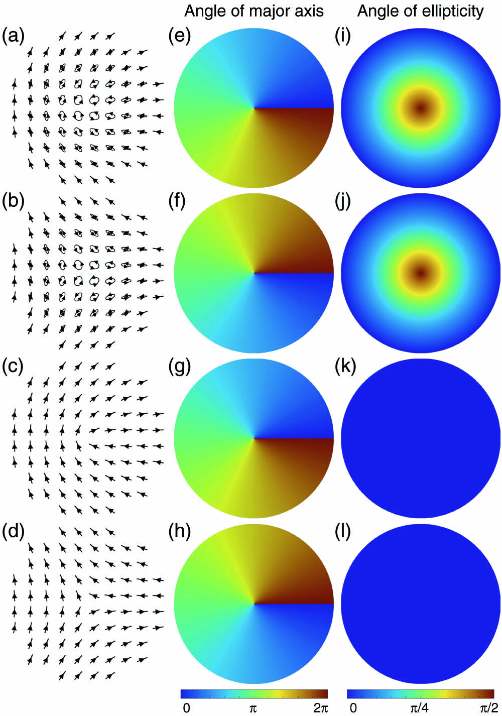
Fig. 1. Distributions of polarization states of four polarization singularities. (a) Lemon C-point with m = 0.5 τ = r m = − 0.5 τ = r m = 0.5 τ = 1 m = − 0.5 τ = 1
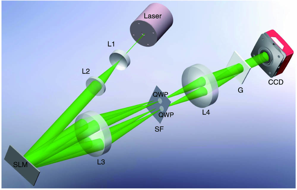
Fig. 2. Schematic of experimental setup. SLM, spatial light modulator; L1, plano-concave lens; L2, plano-convex lens; L3 and L4, bi-convex lenses; SF, spatial filter; QWP, quarter-wave plate; G, Ronchi grating; CCD, charge coupled device.
Fig. 3. Measured intensity distributions around a lemon V-point (m = 0.5 z = 0.1
Fig. 4. Distributions of the intensity and polarization states around a V-point at a propagation distance z = 0.5 m m = 0.5
Fig. 5. Distributions of the intensity and polarization states around a C-point at a propagation distance z = 0.5 m m = 0.5
Fig. 6. Any polarization state can be seen as a superposition of right- and left-handed circularly polarized components carrying the phases. (a) Polarization states at all points surrounding the V-point are linearly polarized but different in orientation, which are located on the equator of the Poincaré sphere. (b) Polarization states at all points surrounding the C-point are elliptically polarized but different in orientation, which are located on a certain latitude in the northern (or southern) hemisphere of the Poincaré sphere.
Fig. 7. Comparison of the polarization topological index T m
Fig. 8. Distributions of the orientation angles 2 ϕ n = 3 η = 0 n = 3 η = r
Fig. 9. Illustration of the experimentally measured intensity and polarization distribution of the ternary case [(a)–(c)] and the ternary spiral case [(d)–(f)] at a propagation distance z = 0.5 m

Set citation alerts for the article
Please enter your email address
© Copyright 2018-2021 | Chinese Laser Press. All Rights Reserved 沪ICP备15018463号-20