• Chinese Optics Letters
  • Vol. 13, Issue 8, 081405 (2015)
Xiao Zou1, Yuxin Leng1、*, Yanyan Li1, Yanyan Feng2, Peixiong Zhang2, Yin Hang2, and Jun Wang2
Author Affiliations
  • 1State Key Laboratory of High Field Laser Physics, Shanghai Institute of Optics and Fine Mechanics, Chinese Academy of Sciences, Shanghai 201800, China
  • 2Key Laboratory of Materials for High Power Lasers, Shanghai Institute of Optics and Fine Mechanics, Chinese Academy of Sciences, Shanghai 201800, China
  • show less
    DOI: 10.3788/COL201513.081405 Cite this Article Set citation alerts
    Xiao Zou, Yuxin Leng, Yanyan Li, Yanyan Feng, Peixiong Zhang, Yin Hang, Jun Wang. Passively Q-switched mode-locked Tm:LLF laser with a MoS2 saturable absorber[J]. Chinese Optics Letters, 2015, 13(8): 081405 Copy Citation Text show less

    Abstract

    A passively Q-switched mode-locked (QML) Tm:LiLuF4 (LLF) laser with a MoS2 saturable absorber (SA) is demonstrated for the first time, to our best knowledge. For the Q-switching mode, the maximum average output power and Q-switched pulse energy are 583 mW and 41.5 μJ, respectively. When the absorbed power is greater than 7.4 W, the passively QML pulse is formed, corresponding to an 83.3-MHz frequency. The modulation depth in Q-switching envelopes is approximately 50%. Results prove that MoS2 is a promising SA for Q-switched and QML solid-state lasers.

    There are many applications for mode-locked lasers at the eye-safe wavelength of approximately 2 μm; these applications include molecular spectroscopy, noninvasive medical diagnostics, and wind lidar[14]. Gain media-doped Tm or Tm,Ho are widely used for mode-locked lasers in the wavelength range of 1.8–2 μm because of the apparent advantage of directly exciting commercial laser diodes at around 800 nm[510]. To date, many hosts have been applied to Tm-based crystals for mode-locking operation, including Y3Al5O12[5], YAlO3[6,7], and YLiF4[8]. Compared with other Tm crystals, Tm:LiLuF4 (LLF) has large emission cross section, long fluorescence lifetime, and low phonon energy[1113]. Passively Q-switched mode-locked (QML) lasers with Nd crystals were proven theoretically and experimentally in previous works[1416]. However, to our knowledge, no studies about passively Q-switched mode-locking based on Tm:LLF lasers have been published.

    Saturable absorbers (SAs) for passively QML and mode-locked 2μm lasers have various types, such as semiconductor SA mirrors[3], carbon nanotubes[6], and graphene[7,8]. Transition metal dichalcogenides (TMDCs) are abundant systems composed of conductors, semi-conductors, and insulators, such as MoS2, MoSe2, and WS2. In addition, TMDCs are possibly prepared for 2D nano-systems because of the weak van der Waals force between the molecular layers[17]. Mode-locked fiber lasers that use MoS2 as SA are widely reported[1820]. However, only a few studies on solid-state mode-locked lasers based on MoS2 SA have been published. In 2015, Kong et al. demonstrated a QML Tm:calcium lithium niobium gallium garnet laser with a MoS2 SA mirror. The maximum average output power and the highest pulse energy of the Q-switched envelope are 62 mW and 0.72 μJ, respectively[21].

    In this Letter, a passively QML Tm:LLF laser with a MoS2 SA is demonstrated for the first time, to our best knowledge. For the Q-switching mode, the maximum average output power and Q-switched pulse energy were 583 mW and 41.5 μJ, respectively. When the absorbed power was greater than 7.4 W, QML pulses were achieved, corresponding to a frequency of 83.3 MHz. The modulation depth in the Q-switching envelopes was approximately 50%. To our knowledge, this is the first time that Q-switched mode-locking has been realized for a Tm:LLF crystal. In addition, the >500mW average output power and >40μJ pulse energy indicate that MoS2 is a promising SA for Q-switched and QML solid-state lasers.

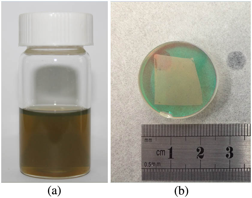
    The liquid-phase exfoliation method was carried out to produce layered MoS2 dispersions[22]. MoS2 powders were dispersed in an aqueous solution of the surfactant sodium cholate (SC) (concentration CSC=1.5mg/mL) with a concentration of 5 mg/mL. MoS2 dispersions were sonicated using a point probe (flathead sonic tip) with a power output of 285 W for 60 min and then centrifuged at 3000 rpm for 90 min. MoS2 dispersions were obtained by collecting the top 3/4 of the centrifuged samples, as shown in Fig. 1(a). MoS2 films were obtained using the vacuum filtration method[22]. MoS2–SC dispersions were diluted by further sonication for 1 h and vacuum filtration with a membrane (225 nm aperture). The obtained wet membranes were transferred to the high-reflectivity (HR) mirror (1850–2050 nm) and then dried at 60°C for 6 h. The MoS2 films on the HR mirror were obtained after the membranes were removed with acetone, as shown in Fig. 1(b).

    (a) MoS2 dispersion without dilution; (b) MoS2 neat film on HR mirror.

    Figure 1.(a) MoS2 dispersion without dilution; (b) MoS2 neat film on HR mirror.

    The experimental setup of the passively QML Tm:LLF laser with MoS2 as the SA is illustrated in Fig. 2. A 1 at.% doping Tm:LLF crystal grown using the Czochralski method had dimensions of 3mm×3mm×12mm. The uncoated crystal, which was polished on both sides, was supplied by the Shanghai Institute of Optics and Fine Mechanics. The crystal was wrapped with an indium foil and placed in water-cooled copper blocks with a temperature of 12°C. The passively QML Tm:LLF laser was pumped by a 793 nm diode laser, which was fiber-coupled with a diameter of 400 μm and NA=0.22. A system of lens with beam profile ratio of 1:1 was used to focus the pump beam to the gain medium. The total optical cavity length was approximately 1803 mm with L1=410mm, L2=420mm, L3=800mm, and L4=150mm, where L1 is the length from the back side of the Tm:LLF to the output couple. Without considering the thermal lens effect, the laser beam diameter was calculated to be approximately 360 μm at the left surface of the Tm:LLF crystal. The transmission of the output couple mirror was 1% at 1950 nm, and the two output beams were similar in power and pulse shape. Furthermore, a band pass filter was used to filter out the remnant pump laser and obtain the pure signal.

    Schematic of the experimental setup.

    Figure 2.Schematic of the experimental setup.

    The average output power versus absorbed power for the continuous wave (CW) and passively QML Tm:LLF laser are demonstrated in Fig. 3. The CW output was obtained using a setup similar to QML but without MoS2. The powers of pump radiation before and after focusing through the Tm:LLF crystal were 100 and 29.9 mW, respectively, corresponding to an absorption of 70.1%. The Q-switched mode-locking operation appeared when the absorbed pump power reached 7.4 W. The slope efficiency of the QML Tm:LLF laser decreased by 11.7%, which contained the loss of MoS2. The maximum output power was 583 mW, corresponding to an absorbed power of 22 W. The pulse width is indicated in Fig. 4. Pulses have a narrow trance along the absorbed pump power, and approximately 13.97 μs of pulse width was obtained with the maximum output. The frequency and the pulse energy of the Q-switched pulse versus the absorbed power are shown in Fig. 5. With the absorbed power changing from 7.4 to 22 W, the frequency increased from 7.9 to 13.9 kHz, and the pulse energy increased from 11.8 to 41.5 μJ.

    Average output power versus absorbed power.

    Figure 3.Average output power versus absorbed power.

    Pulse width versus absorbed power.

    Figure 4.Pulse width versus absorbed power.

    Frequency and average energy of the Q-switched envelope versus absorbed power.

    Figure 5.Frequency and average energy of the Q-switched envelope versus absorbed power.

    The Q-switched pulse train is illustrated in Fig. 6(a). The slight jitter can be attributed to the intrinsic nonlinear dynamics of the laser following a deterministic low-dimensional dynamics[23,24]. Moreover, spurious pulses were not observed between the Q-switched pulses. When the absorbed power was greater than 7.4 W and the end-mirror with MoS2 was carefully optimized, the Q-switched mode-locking operation was established. As shown in Figs. 6(b)6(d), the mode-locked pulse train in the Q-switched envelope is illustrated with different divisions, including 10 μs/division [Fig. 6(b)], 800 ns/division [Fig. 6(c)], and 20 ns/division [Fig. 6(d)]. The time interval between the two mode-locked pulses was approximately 12 ns, indicating a frequency of 83.3 MHz. The optical roundtrip cavity length was estimated to be 3606 mm, which accurately matched with the optical length between the two adjacent mode-locked pulses. No damage on the crystal, cavity mirrors, and MoS2 was observed during our work.

    (a) Q-switched pulse train; mode-locked pulse train in the Q-switched envelope with different divisions: (b) 10 μs/division; (c) 800 ns/division; and (d) 20 ns/division.

    Figure 6.(a) Q-switched pulse train; mode-locked pulse train in the Q-switched envelope with different divisions: (b) 10 μs/division; (c) 800 ns/division; and (d) 20 ns/division.

    The spectra of CW and QML operations were measured using a spectrometer (Spectral Production, SM-301-EX) with a resolution of 15 nm. As shown in Fig. 7, the full-width half-maximum of the QML laser was 35 nm with a central wavelength of 1918 nm. Compared with CW operation, the spectrum was slightly broadened and shifted to a shorter wavelength. The possible reasons for the phenomenon include different thermal effects, a larger nonlinear phase based on the higher peak power[21], and limited resolution of the spectroscopy instrument. The CW mode-locking operation was not realized in our work possibly because of the large modulation depth of the MoS2[21]. The near-field beam profile with the TM00 mode is shown in Fig. 7 (inset).

    Spectrum of CW and Q-switched mode-locking operation; inset, beam profile of the QML Tm:LLF laser at maximum output.

    Figure 7.Spectrum of CW and Q-switched mode-locking operation; inset, beam profile of the QML Tm:LLF laser at maximum output.

    In conclusion, we report a passively QML Tm:LLF laser with a MoS2 SA. For the Q-switching mode, the maximum average output power and Q-switched pulse energy are 583 mW and 41.5 μJ, corresponding to a frequency of 14.06 kHz. When the absorbed power is greater than 7.4 W, the Q-switched mode-locking operation is formed with an 83.3 MHz frequency. The modulation depth in Q-switching envelopes is approximately 50%. To our knowledge, this is the first time that Q-switched mode-locking is realized for a Tm:LLF crystal, and the average output power and Q-switched pulse energy are both highest for Q-switched Tm lasers with MoS2. Moreover, the >500mW average output power and >40μJ pulse energy indicate that MoS2 is a promising SA for Q-switched and QML solid-state lasers.

    References

    [1] K. Scholle, S. Lamrini, P. Koopmann, P. Fuhrberg. Frontiers in Guided Wave Optics and Optoelectronics, 471(2010).

    [2] N. S. Nishioka, Y. Domankevitz. IEEE J. Quantum Electron., 26, 2271(1990).

    [3] A. A. Lagatsky, F. Fusari, S. Calvez, J. A. Gupta, V. E. Kisel, N. V. Kuleshov, C. T. A. Brown, D. Dawson, W. Sibbett. Opt. Lett., 34, 2587(2009).

    [4] N. Saidin, D. I. M. Zen, S. S. A. Damanhuri, S. W. Harun, H. Ahmad, F. Ahmad, K. Dimyati, A. Halder, M. C. Paul, M. Pal, S. K. Bhadra. Chin. Opt. Lett., 11, 063201(2013).

    [5] J. F. Pinto, L. Esterowitz, G. H. Rosenblatt. Opt. Lett., 17, 731(1992).

    [6] J. Liu, Y. Wang, Z. Qu, X. Fan. Opt. Laser Technol., 44, 960(2012).

    [7] Y. Peng, X. Wei, W. Wang. Laser Phys. Lett., 9, 15(2012).

    [8] Y. Bai, M. Qi, S. Wang, R. Shi, D. Li, Z. Ren, J. Bai. Appl. Phys. Express, 6, 102701(2013).

    [9] L. Han, B. Yao, X. Duan, S. Li, T. Dai, Y. Ju, Y. Wang. Chin. Opt. Lett., 12, 081401(2014).

    [10] X. Yang, Y. Chen, C. Zhao, H. Zhang. Chin. Opt. Lett., 12, 031405(2014).

    [11] N. Coluccelli, G. Galzerano, P. Laporta, F. Cornacchia, D. Parisi, M. Tonelli. Opt. Lett., 32, 2040(2007).

    [12] N. Coluccelli, G. Galzerano, D. Parisi, M. Tonelli, P. Laporta. Opt. Lett., 33, 1951(2008).

    [13] J. Xiong, H. Y. Peng, C. C. Zhao, Y. Hang, L. H. Zhang, M. Z. He, X. M. He, G. Z. Chen. Laser Phys. Lett., 6, 868(2009).

    [14] Y.-F. Chen, J.-L. Lee, H.-D. Hsieh, S.-W. Tsai. IEEE J. Quantum Electron., 38, 312(2002).

    [15] F. Q. Liu, J. L. He, J. L. Xu, B. T. Zhang, J. F. Yang, J. Q. Xu, C. Y. Gao, H. J. Zhang. Laser Phys. Lett., 6, 567(2009).

    [16] S.-D. Pan, L. Cui, J.-Q. Liu, B. Teng, J.-H. Liu, X.-H. Ge. Opt. Mater., 38, 42(2014).

    [17] K. Wang, J. Wang, J. Fan, M. Lotya, A. O’Neill, D. Fox, Y. Feng, X. Zhang, B. Jiang, Q. Zhao, H. Zhang, J. N. Coleman, L. Zhang, W. J. Blau. ACS Nano, 7, 9260(2013).

    [18] F. Wang, A. G. Rozhin, V. Scardaci, Z. Sun, F. Hennrich, I. H. White, W. I. Milne, A. C. Ferrarl. Nat. Nanotechnol., 3, 738(2008).

    [19] J. Du, Q. Wang, G. Jiang, C. Xu, C. Zhao, Y. Xiang, Y. Chen, S. Wen, H. Zhang. Sci. Rep., 4, 6346(2014).

    [20] H. Xia, H. Li, C. Lan, C. Li, X. Zhang, S. Zhang, Y. Liu. Opt. Express, 22, 17341(2014).

    [21] L. Kong, G. Xie, P. Yuan, L. Qian, S. Wang, H. Yu, H. Zhang. Photon. Res., 3, A47(2015).

    [22] X. Zhang, S. Zhang, C. Chang, Y. Feng, Y. Li, N. Dong, K. Wang, L. Zhang, W. J. Blau, J. Wang. Nanoscale, 7, 2978(2015).

    [23] D. Y. Tang, S. P. Ng, L. J. Qin, X. L. Meng. Opt. Lett., 28, 325(2003).

    [24] M. Kovalsky, A. Hnilo. Opt. Lett., 35, 3498(2010).

    Xiao Zou, Yuxin Leng, Yanyan Li, Yanyan Feng, Peixiong Zhang, Yin Hang, Jun Wang. Passively Q-switched mode-locked Tm:LLF laser with a MoS2 saturable absorber[J]. Chinese Optics Letters, 2015, 13(8): 081405
    Download Citation