• High Power Laser Science and Engineering
  • Vol. 3, Issue 1, 010000e7 (2015)
Dongfeng Zhao1、2, Li Wan1, Zunqi Lin1, Pin Shao1, and and Jianqiang Zhu1
Author Affiliations
  • 1Shanghai Institute of Optics and Fine Mechanics, Chinese Academy of Sciences, No. 390, Qinghe Road, Jiading District, Shanghai 201800, China
  • 2University of Chinese Academy of Sciences, No. 19A Yuquan Road, Beijing 100049, China
  • show less
    DOI: 10.1017/hpl.2015.1 Cite this Article Set citation alerts
    Dongfeng Zhao, Li Wan, Zunqi Lin, Pin Shao, and Jianqiang Zhu. SG-II-Up prototype final optics assembly: optical damage and clean-gas control[J]. High Power Laser Science and Engineering, 2015, 3(1): 010000e7 Copy Citation Text show less
    The prototype FOA is composed of fixed interfaces to the target chamber and five modules that house eight full-aperture optics. The clear aperture size is .
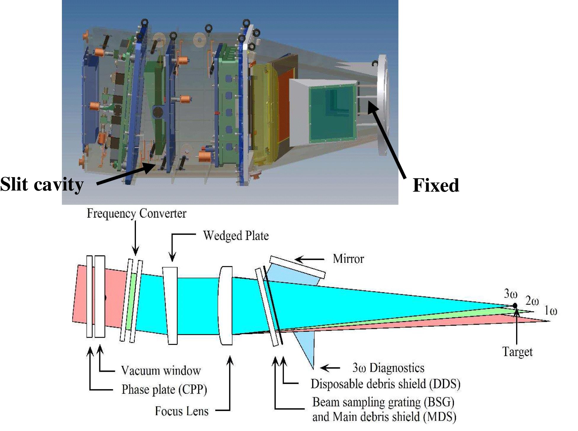
    Fig. 1. The prototype FOA is composed of fixed interfaces to the target chamber and five modules that house eight full-aperture optics. The clear aperture size is .
    Numerical model of the FOA generated by ICEMCFD.
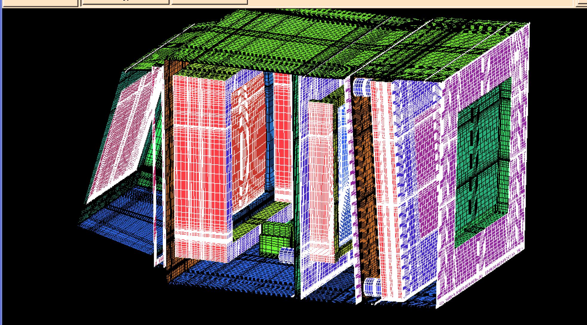
    Fig. 2. Numerical model of the FOA generated by ICEMCFD.
    Schematic of the observed cross-section distributions in the prototype FOA.
    Fig. 3. Schematic of the observed cross-section distributions in the prototype FOA.
    Density distribution of the contaminants in cross-section 2 as the flux ranges within after 30 s.
    Fig. 4. Density distribution of the contaminants in cross-section 2 as the flux ranges within after 30 s.
    Distribution of the gas inlets and outlets in the FOA.
    Fig. 5. Distribution of the gas inlets and outlets in the FOA.
    Two types of inlet and exhaust pipes.
    Fig. 6. Two types of inlet and exhaust pipes.
    Graph showing the real-time contaminant quantity.
    Fig. 7. Graph showing the real-time contaminant quantity.
    Surface damage morphologies induced by contaminants: (a) film damage located on the clear aperture brim, (b) surface spot outside the clear aperture, (c) clear aperture brim and (d) surface ‘mooning’ damage outside the clear aperture.
    Fig. 8. Surface damage morphologies induced by contaminants: (a) film damage located on the clear aperture brim, (b) surface spot outside the clear aperture, (c) clear aperture brim and (d) surface ‘mooning’ damage outside the clear aperture.
    Results obtained by x-ray fluorescence spectrometry: (a) unused silica coated by sol-gel film (including Al, Si, Pd, Cr, Mn, Fe, Cu and Zn) and (b) used silica coated by sol-gel film (including Zn, Al, Si, P, S, K, Ca, Ti, Cr, Mn, Fe, Ni and Cu; because the Pb amount is negligible, it is not labeled).
    Fig. 9. Results obtained by x-ray fluorescence spectrometry: (a) unused silica coated by sol-gel film (including Al, Si, Pd, Cr, Mn, Fe, Cu and Zn) and (b) used silica coated by sol-gel film (including Zn, Al, Si, P, S, K, Ca, Ti, Cr, Mn, Fe, Ni and Cu; because the Pb amount is negligible, it is not labeled).
    Dongfeng Zhao, Li Wan, Zunqi Lin, Pin Shao, and Jianqiang Zhu. SG-II-Up prototype final optics assembly: optical damage and clean-gas control[J]. High Power Laser Science and Engineering, 2015, 3(1): 010000e7
    Download Citation