
Xin-Zhe Zhu, Wei-Yuan Liu, Min Chen. Effects of slant angle of sharp plasma-vacuum boundary on electron injection in laser wakefield acceleration [J]. Acta Physica Sinica, 2020, 69(3): 035201-1
- Acta Physica Sinica
- Vol. 69, Issue 3, 035201-1 (2020)
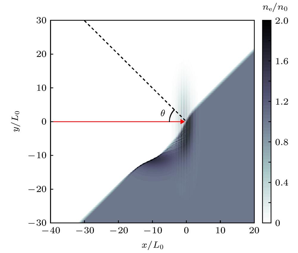
Fig. 1. Schematic of vacuum-plasma boundary injection in laser wakefield acceleration真空等离子体边界激光尾波电子注入示意图
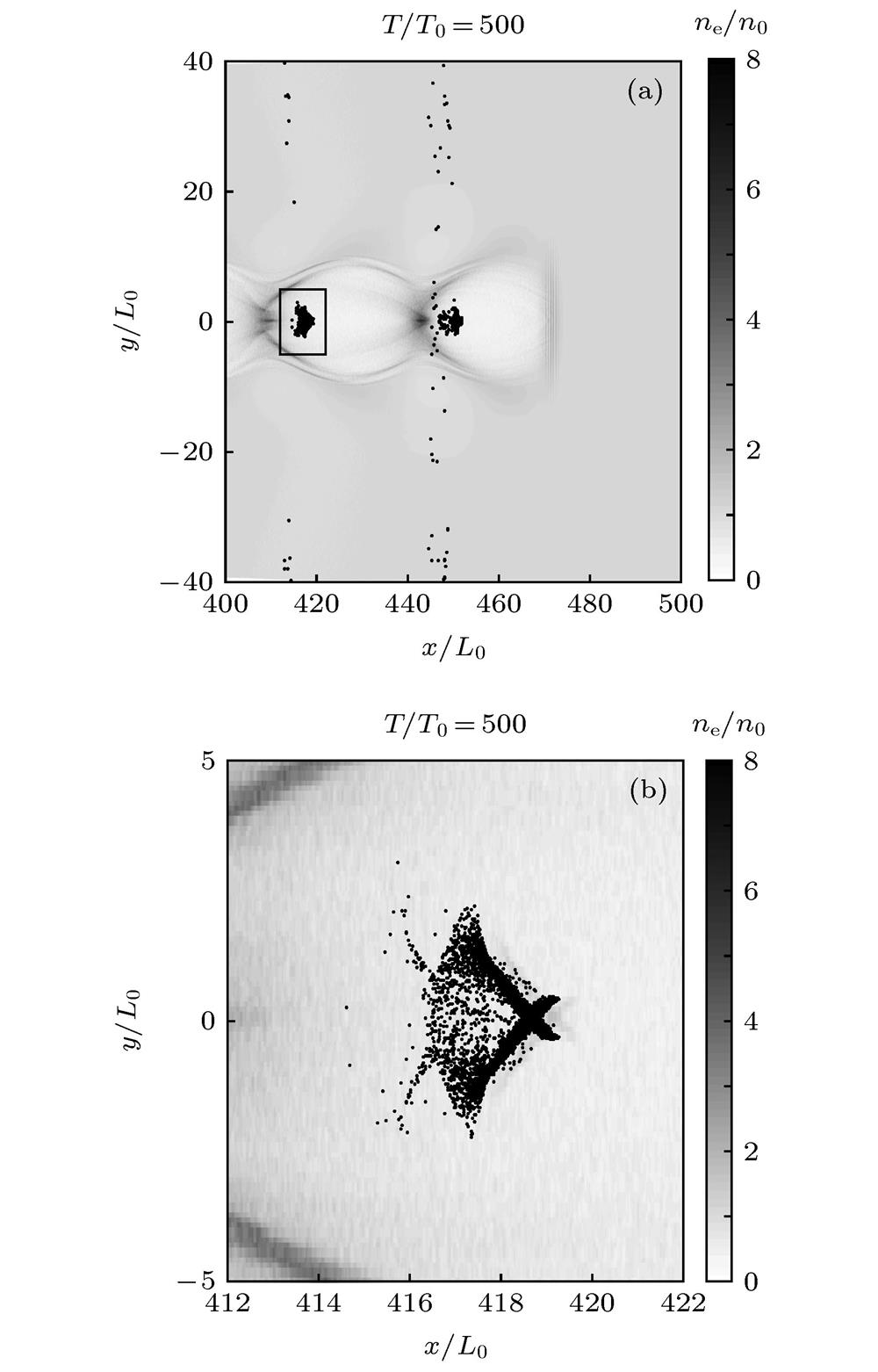
Fig. 2. Distributions of plasma density and injected electrons after 500T 0 propagation when the boundary slant angle is 0°: (a) Injected electrons; (b) electrons in the second bubble
倾斜角为0°时激光传播500T 0后等离子体密度与注入电子(γ ≥ 15)的位置分布 (a)注入电子的分布; (b)放大后第二个空泡中的电子分布
Fig. 3. Average energy growth with time: (a) Average gamma factor of electrons in the first bubble; (b) average gamma factor of electrons in the second bubble激光传播过程中不同角度下的电子平均能量增长的情况 (a)第一个空泡内电子平均相对论因子γ 的变化; (b) 第二个空泡内电子平均相对论因子γ 的变化
Fig. 4. Electrons statistics after same acceleration length: (a) Average energy; (b) total acceleration charge (normalized to pC/μm).不同角度下电子注入后经过相同加速距离后的加速情况对比 (a)被加速电子的平均能量; (b)被加速电子的总电量(单位归一化到 pC/μm)
Fig. 5. Trajectories of electrons in the first bubble (red) and second bubble (blue): (a) 0°; (b) 45°. Ten electrons’ trajectories have been selected for clearer view不同倾斜角度下的第一个空泡(红色)和第二个空泡(蓝色)中注入电子的轨迹(为了显示清晰, 对两种倾角情形, 各自只选取了10个典型的电子) (a) 0°; (b) 45°
Fig. 6. (a) Average transverse momentum of electrons in the first bubble (red) and second bubble (blue) when the boundary slant angle is 0°; (b) average transverse momentum of electrons in the first bubble (red) and second bubble (blue) when the boundary slant angle is 45°(a) 0°倾斜边界角时注入空泡1 (红)和空泡2上下两侧注入电子(蓝)的平均动量; (b) 45°倾斜边界角时注入空泡1和空泡2电子的平均动量
Fig. 7. Electrons’ injection trajectories when the boundary slant angle is 0°: (a) T /T 0 = 20; (b) T /T 0 = 40; (c) T /T 0 = 60; (d) T /T 0 = 90. Here the background color bar represents the plasma density, we have selected 3 particles with equally separation along the transverse direction. The blue and red lines represent the injection trajectories and the circles represent the particles’ positions at that time
倾斜边界角为0°时的电子注入过程(等横向间距选取了3个粒子作为示意, 背景为等离子体密度, 线条代表粒子的真实轨迹, 圆圈代表粒子在该时刻的位置) (a) T /T 0 = 20; (b) T /T 0 = 40; (c) T /T 0 = 60; (d) T /T 0 = 90
Fig. 8. Electrons injection at 45° incidence: (a) T /T 0 = 40; (b) T /T 0 = 60; (c) T /T 0 = 80; (d) T /T 0 = 110
45°入射下边界面产生电子注入的过程 (a) T /T 0 = 40; (b) T /T 0 = 60; (c) T /T 0 = 80; (d) T /T 0 = 110
Fig. 9. (a) Original positions of the trapped electrons when the boundary slant angle is 0°; (b) original positions of the trapped electrons when the boundary slant angle is 45°(a)倾斜边界为0°情况下第一个空泡和第二个空泡内注入电子的起始位置; (b) 倾斜边界为45°入射下第一个空泡和第二个空泡内注入电子的起始位置
|
Table 1.
Injection charge of S-polarization and P-polarization incidence at 45°.
S偏振和P偏振激光45°入射时注入空泡中的电子电量

Set citation alerts for the article
Please enter your email address
© Copyright 2018-2021 | Chinese Laser Press. All Rights Reserved 沪ICP备15018463号-20