• Photonics Research
  • Vol. 11, Issue 2, 270 (2023)
S. Francesconi1, A. Raymond1, R. Duhamel1, P. Filloux1, A. Lemaître2, P. Milman1, M. I. Amanti1, F. Baboux1、*, and S. Ducci1
Author Affiliations
  • 1Université Paris Cité, CNRS, Laboratoire Matériaux et Phénomènes Quantiques, 75013 Paris, France
  • 2Université Paris-Saclay, CNRS, Centre de Nanosciences et de Nanotechnologies, 91120 Palaiseau, France
  • show less
    DOI: 10.1364/PRJ.459879 Cite this Article Set citation alerts
    S. Francesconi, A. Raymond, R. Duhamel, P. Filloux, A. Lemaître, P. Milman, M. I. Amanti, F. Baboux, S. Ducci. On-chip generation of hybrid polarization-frequency entangled biphoton states[J]. Photonics Research, 2023, 11(2): 270 Copy Citation Text show less
    (a) Schematic of an AlGaAs ridge microcavity emitting counterpropagating twin photons by SPDC in a transverse pump geometry. Two type-II interactions occur, generating either an H-polarized signal photon and a V-polarized idler photon (interaction HV), or the opposite situation (interaction VH), resulting in a hybrid polarization–frequency entangled state. (b) Calculated SPDC tunability curve, showing the central wavelengths of signal and idler photons as a function of the pump incidence angle θ (with respect to the vertical x axis), for both interactions, using our sample properties and pump central wavelength λp=773.15 nm. (c) Sketch of the experimental setup to measure the HOM interference of the hybrid polarization–frequency state. HWP, half-wave plate; F, frequency filter; FPC, fibered polarization controller; BS, beam splitter; SNSPD, superconducting nanowire single-photon detector; TDC, time-to-digital converter.
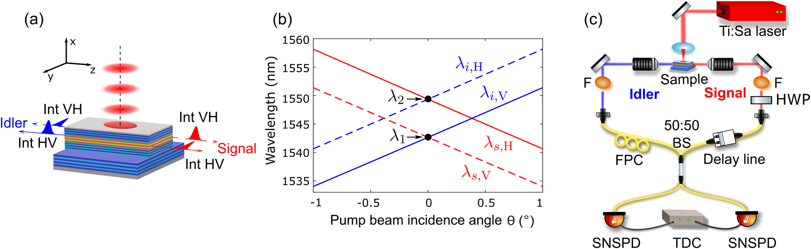
    Fig. 1. (a) Schematic of an AlGaAs ridge microcavity emitting counterpropagating twin photons by SPDC in a transverse pump geometry. Two type-II interactions occur, generating either an H-polarized signal photon and a V-polarized idler photon (interaction HV), or the opposite situation (interaction VH), resulting in a hybrid polarization–frequency entangled state. (b) Calculated SPDC tunability curve, showing the central wavelengths of signal and idler photons as a function of the pump incidence angle θ (with respect to the vertical x axis), for both interactions, using our sample properties and pump central wavelength λp=773.15  nm. (c) Sketch of the experimental setup to measure the HOM interference of the hybrid polarization–frequency state. HWP,  half-wave plate; F, frequency filter; FPC, fibered polarization controller; BS, beam splitter; SNSPD, superconducting nanowire single-photon detector; TDC, time-to-digital converter.
    (a) Simulated joint spectral intensity (JSI) of the hybrid polarization–frequency biphoton state of Eq. (3), assuming Gaussian phase-matching functions (see text for details). (b) Corresponding simulated HOM interferogram, showing a sinusoidal oscillation modulated by a Gaussian envelope.
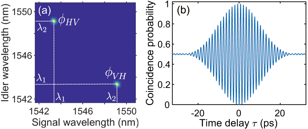
    Fig. 2. (a) Simulated joint spectral intensity (JSI) of the hybrid polarization–frequency biphoton state of Eq. (3), assuming Gaussian phase-matching functions (see text for details). (b) Corresponding simulated HOM interferogram, showing a sinusoidal oscillation modulated by a Gaussian envelope.
    (a) Measured joint spectral intensity (JSI) of the hybrid polarization–frequency state, and (b) corresponding marginal spectrum of signal (red line) and idler (blue line) photons. (c) Measured HOM interferogram (black symbols with error bars) fitted with Eq. (8) (blue line). Data points show raw (uncorrected) coincidence counts.
    Fig. 3. (a) Measured joint spectral intensity (JSI) of the hybrid polarization–frequency state, and (b) corresponding marginal spectrum of signal (red line) and idler (blue line) photons. (c) Measured HOM interferogram (black symbols with error bars) fitted with Eq. (8) (blue line). Data points show raw (uncorrected) coincidence counts.
    Experimental reconstruction of the restricted density matrix [Eq. (9)] of the biphoton state in the hybrid polarization–frequency discrete space (the imaginary part is zero by construction).
    Fig. 4. Experimental reconstruction of the restricted density matrix [Eq. (9)] of the biphoton state in the hybrid polarization–frequency discrete space (the imaginary part is zero by construction).
    Hong–Ou–Mandel scheme for a counterpropagating parametric source emitting photons through both HV and VH interactions and considering the cavity effect induced by the waveguide facets. The letters refer to the subscripts used in the calculations.
    Fig. 5. Hong–Ou–Mandel scheme for a counterpropagating parametric source emitting photons through both HV and VH interactions and considering the cavity effect induced by the waveguide facets. The letters refer to the subscripts used in the calculations.
    Simulated HOM interferogram for the HPF entangled state, taking into account the Fabry–Pérot effect of the sample with facet reflectivity R=10%. From (a) to (c), the time axis is zoomed around τ=0 to show the additional modulation at the pump frequency. The scattered points are caused by numerical artifacts in the integration.
    Fig. 6. Simulated HOM interferogram for the HPF entangled state, taking into account the Fabry–Pérot effect of the sample with facet reflectivity R=10%. From (a) to (c), the time axis is zoomed around τ=0 to show the additional modulation at the pump frequency. The scattered points are caused by numerical artifacts in the integration.
    Simulated HOM interferogram obtained from the data of Fig. 6 by averaging out modulation at the pump frequency, leading to a decrease of effective fringe visibility.
    Fig. 7. Simulated HOM interferogram obtained from the data of Fig. 6 by averaging out modulation at the pump frequency, leading to a decrease of effective fringe visibility.
    S. Francesconi, A. Raymond, R. Duhamel, P. Filloux, A. Lemaître, P. Milman, M. I. Amanti, F. Baboux, S. Ducci. On-chip generation of hybrid polarization-frequency entangled biphoton states[J]. Photonics Research, 2023, 11(2): 270
    Download Citation