
F. Wang, S. Slivken, M. Razeghi. Harmonic injection locking of high-power mid-infrared quantum cascade lasers[J]. Photonics Research, 2021, 9(6): 1078
- Photonics Research
- Vol. 9, Issue 6, 1078 (2021)
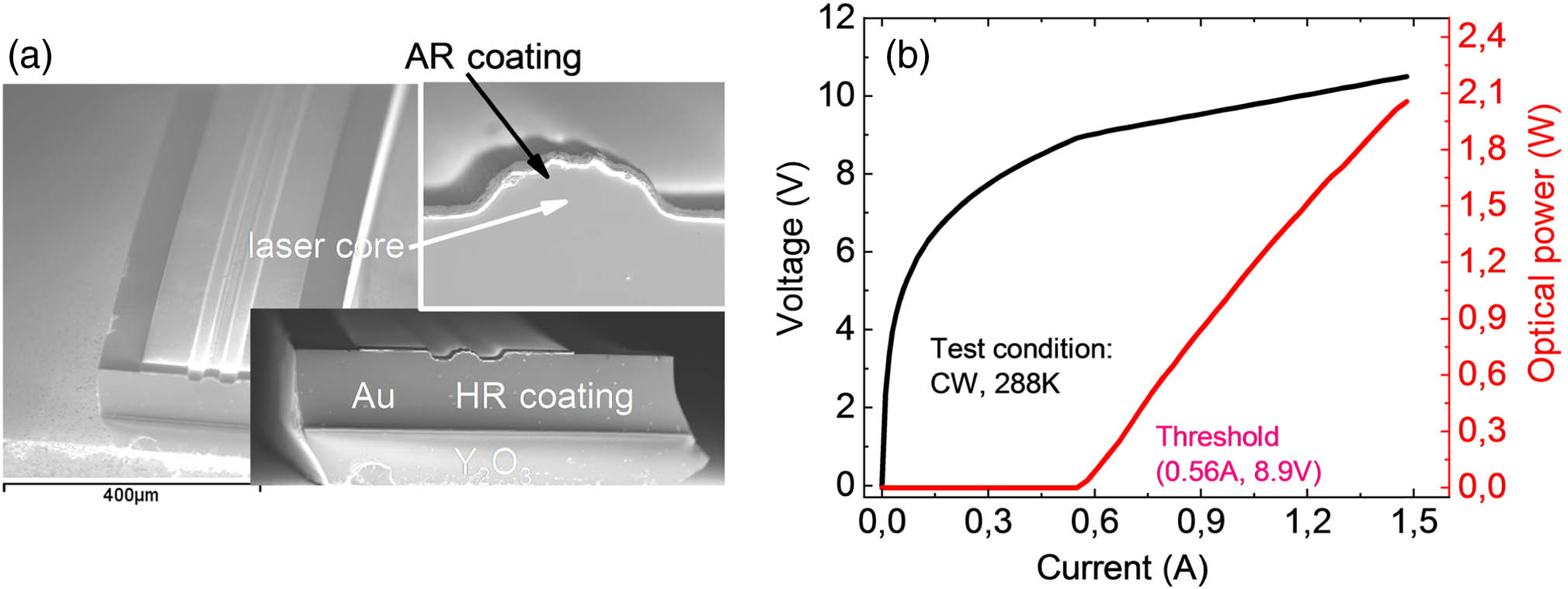
Fig. 1. (a) The scanning electron microscopy (SEM) image of the QCL device and its HR coated and AR coated facets. (b) Light-current-voltage (LIV) curves of this QCL.
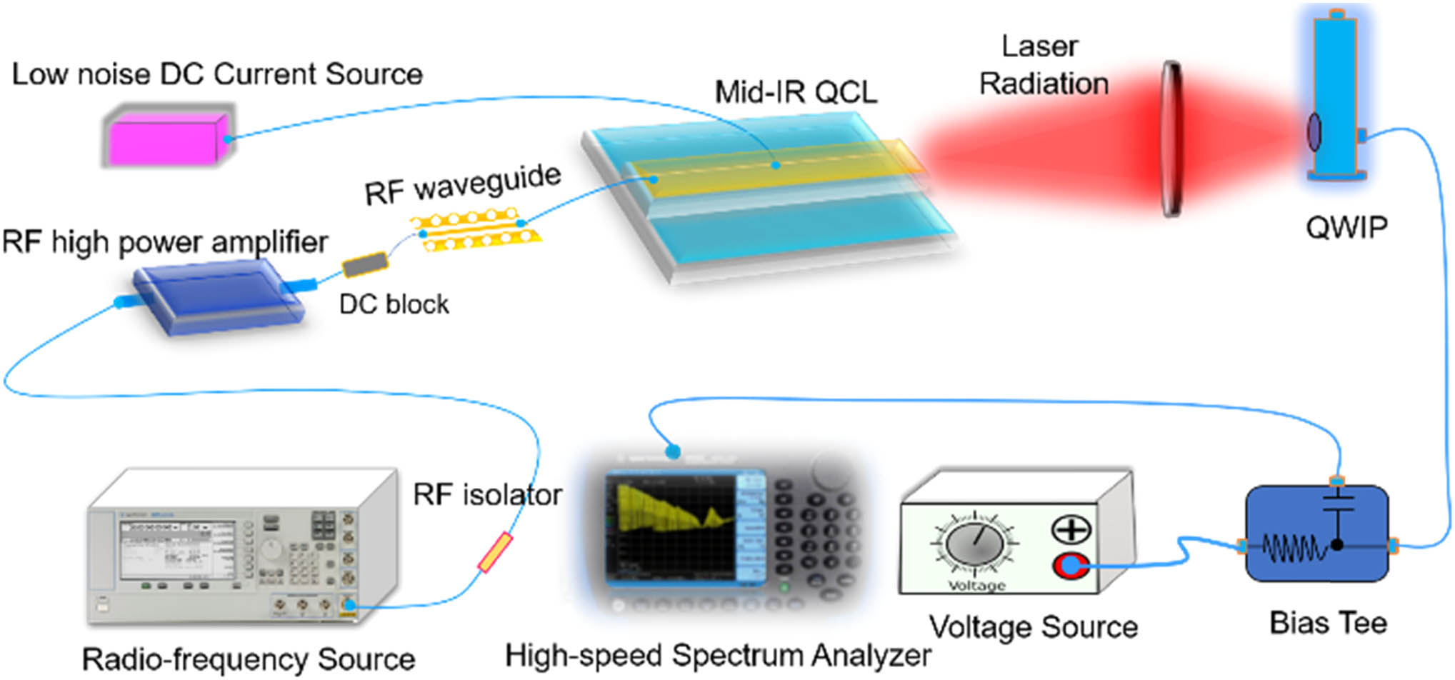
Fig. 2. Experimental setup. The mid-infrared QCL is biased by a low-noise DC current source. Laser emission is coupled into a quantum well infrared photodetector (QWIP). The high frequency components of the photocurrents are coupled into a spectrum analyzer. RF waves are generated by a RF generator and amplified by a high-power amplifier. The RF signal is injected into the QCL through a high-speed RF waveguide from near the back facet of the QCL.
Fig. 3. (a) The evolution of the beat note (continuous branch) of the QCL as a function of the injected RF frequency (discrete branch) (each injected RF frequency can be found in the x δ f RF Δ f 0 δ f RF − b eatnote δ δ f RF − b eatnote
Fig. 4. Spectrum of the laser emission under resonance and off-resonance conditions.
Fig. 5. Beat note evolution as a function of operating temperature. The vertical line is the injected RF signal, and the other branch is the beat note.
Fig. 6. (a) First-order and second-harmonic beat note. (b) The evolution of the beat note as a function of injected RF frequency. The discrete branch is the RF signal, and the continuous branch represents the beat note. (Each injected RF frequency can be found in the x

Set citation alerts for the article
Please enter your email address
© Copyright 2018-2021 | Chinese Laser Press. All Rights Reserved 沪ICP备15018463号-20