Abstract
We present the generation of the nanosecond cylindrical vector beams (CVBs) in a two-mode fiber (TMF) and its applications of stimulated Raman scattering. The nanosecond (1064 nm, 10 ns, 10 Hz) CVBs have been directly produced with mode conversion efficiency of ~18 dB (98.4%) via an acoustically induced fiber grating, and then the stimulated Raman scattering signal is generated based on the transmission of the nanosecond CVBs in a 100-m-long TMF. The transverse mode intensity and polarization distributions of the first-order Stokes shift component (1116.8 nm) are consistent with the nanosecond CVBs pump pulse.1. Introduction
Recently, the free-space-based cylindrical vector beams (CVBs) have attracted much attention. Because CVBs possess polarization singularity in case of tight focusing, the CVBs have been extensively explored in many fields, such as the nonlinear effect enhancement[1], tip-enhanced Raman spectroscopy (TERS)[2–4], molecular orientation examination[5], dark-state excitation[6], micro/nano fabrication[7], and optical tweezers[8]. In addition, it is noteworthy that the optical-fiber-based CVBs would also open up various applications, such as fiber CVBs-based communications[9], fiber CVBs-based sensing[10], backgroundless plasmonic tip nanofocusing[11], quantum entanglement[12], stimulated emission depletion microscopy (STED)[13], and surface-enhanced Raman spectroscopy (SERS)[14].
Up to now, CVBs have been generated in optical fibers using many methods, such as the mechanical micro-bend fiber grating[15], long-period fiber grating fabricated using laser[16,17], and fiber fused coupler[18–20]. However, those methods lack precise wavelength tunability. In addition, the optical fiber is only used as a medium for conducting CVBs in these applications mentioned above. When the CVBs pulse transmits over long distances in optical fibers, nonlinear phenomena will appear due to the interaction between the CVBs pulse with extremely high peak power and the optical fiber[21,22], although the nonlinear effect of the fiber core is very weak. For instance, the stimulated Raman scattering (SRS) spectra up to the fourth-order Stokes shift component have been experimentally observed in a 100-m-long hollow-core ring fiber pumped by a nanosecond pulse with radial polarization distribution[18], and each-order Stokes shift component also has radial polarization characteristics. This nonlinear frequency conversion process can create coherent radial vector beams within a span of hundreds of nanometers. Nevertheless, it does not show the nonlinear transmission characteristic of the nanosecond pulse with linear polarization and azimuthal polarization distributions, because it is difficult to switch in-situ the linear, radial, and azimuthal vector beams in optical fibers using the mechanical micro-bend grating with a fixed grating period.
In this paper, the nanosecond (1064 nm, 10 ns, 10 Hz) CVBs have been directly produced in a two-mode fiber (TMF) via an acoustically induced fiber grating (AIFG), and then the SRS signal is generated based on the transmission of the nanosecond CVBs in a 100-m-long TMF. The transverse mode intensity and polarization of the first-order Stokes shift component are consistent with the nanosecond CVBs pump pulse.
Sign up for Chinese Optics Letters TOC. Get the latest issue of Chinese Optics Letters delivered right to you!Sign up now
2. Experimental Results and Discussion
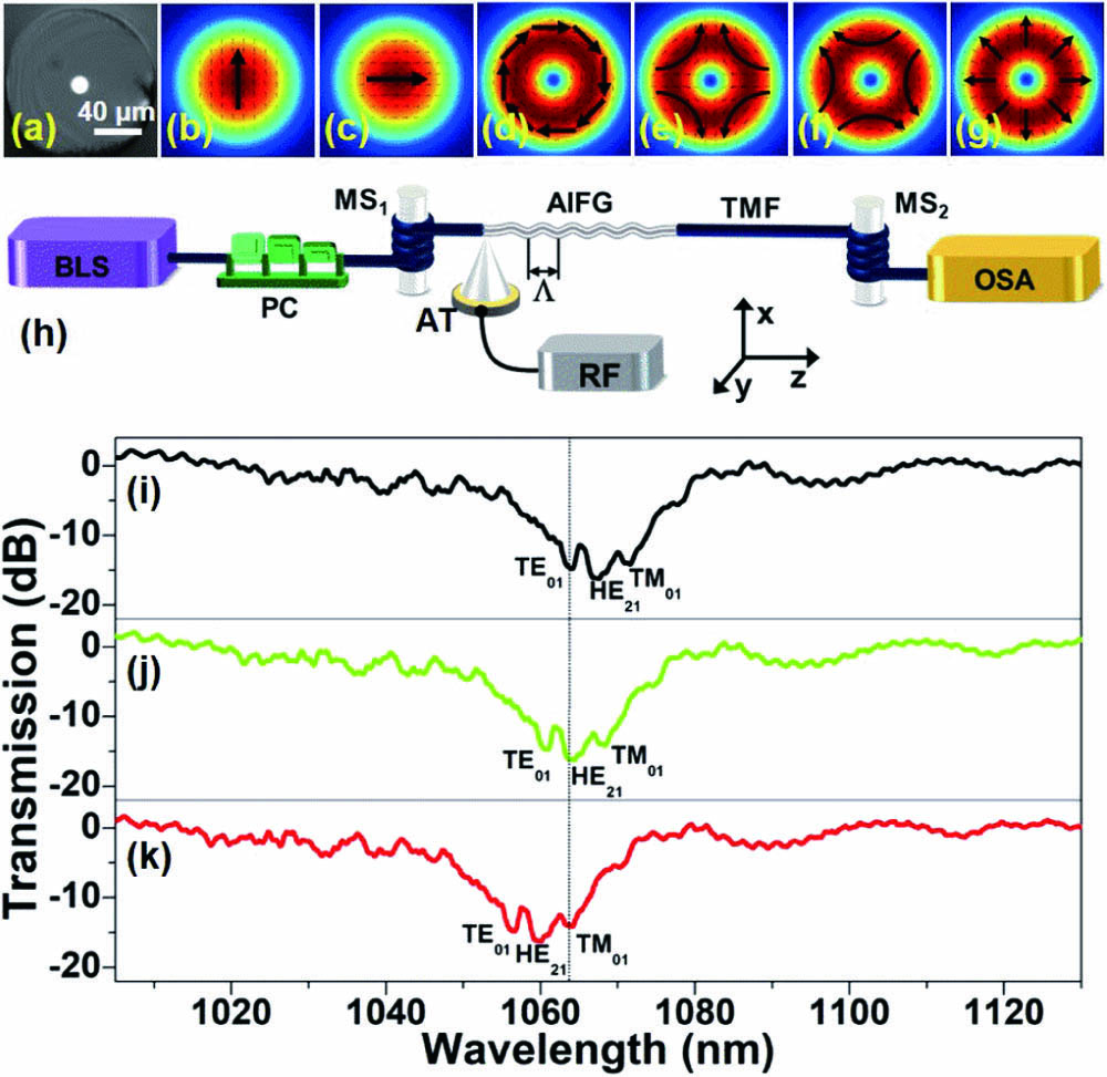
Figure 1(a) is the microscope image of the TMF with core radius of 4.5 µm. The refractive indices of the core and cladding are 1.4681 and 1.4628 at 1550 nm. The dispersion and loss are and 0.74 dB/km at 1064 nm, respectively. The transverse mode intensity distributions of hybrid electric (HE) modes, and , at 1064 nm are shown in Figs. 1(b) and 1(c), respectively. Figures 1(d)–1(g) are the transverse mode intensity distributions of the first group high-order vector modes of , , and , respectively. Figure 1(h) is the experimental configuration of AIFG constructed with a TMF, and the separation characteristics of the high-order degenerate vector modes can be examined based on the transmission spectra of the AIFG[23,24]. A supercontinuum is adopted as the broadband light source (BLS), and then a fiber in-line polarization controller (PC) is used to adjust the polarization characteristic of the BLS. A mode stripper () is inserted between the PC and AIFG to eliminate the effects of the unwanted high-order vector modes (, , ) to ensure an mode incident into the AIFG[25,26]. The acousto-optic interaction length of AIFG is 10 cm, and the diameter of the TMF is etched to 28 µm[27].

Figure 1.(a) Microscope image of TMF; (b) and (c) transverse modal intensity of HEx11 and HEy11 modes; (d)–(g) transverse modal intensity of , , , and modes; (h) experimental configuration for measuring the transmission spectra of AIFG; (i)–(k) spectral tunability of AIFG with three separated resonance peaks, corresponding to the coupling between HEx/y11 and , , modes, respectively.
With an appropriate radio frequency (RF) driving signal loaded to the acoustic transducer (AT), an AIFG can be generated with help of the propagation of the linearly polarized acoustic flexural wave along the unjacketed TMF[28]. When the light from BLS transmits along the AIFG, can be coupled to , , and modes in case of the phase-matching condition to be satisfied, with being the beat length between and , , modes, and Λ being the grating period of AIFG[29]. Furthermore, the other , with the same parameter as , is connected to the output terminal of the TMF to filter out the high-order vector mode to keep the mode in the fiber core. The spectral tunabilities of the AIFG are examined using an optical spectrum analyzer (OSA). Figures 1(c)–1(e) are the measurement results, when three RF signals, with , 1.346, and 1.360 MHz, are loaded to the AT, respectively. Note that the resonance wavelength shifts toward short wavelengths by increasing the RF. The transmission spectrum has three separated resonance peaks with a central wavelength interval of ∼3.8 nm, which means that the high-order vector modes have been effectively separated[23], and the three separated resonance peaks are corresponding to the conversion between and , , , respectively.
Figure 2 is the experimental configuration for generating the nanosecond CVBs in the TMF. At the input terminal, the BLS is replaced by a 1064 nm nanosecond laser (pulse width: 10 ns, repetition frequency: 10 Hz). The nanosecond pulse is linearly polarized via a polarizer (P), and then a half-wave plate (HWP) is inserted to adjust the polarization orientation of the nanosecond pulse. An average power of 42 mW is measured for the nanosecond pulse before injected into the TMF via a micro-objective (). An MS is connected to the input terminal of the AIFG to ensure that only the mode is incident into the AIFG[25]. When the fundamental vector mode ( or ) propagates along the AIFG, and can be, respectively, coupled to and by the AIFG[26]. The generated CVBs (, ) transmit in the TMF for a length of and then are output from the TMF after collimating via . The CVB is reflected by a beam splitter (BS) and then captured by a charge coupled device (CCD). Furthermore, the polarization characteristic of the CVB is examined by putting a P between the BS and CCD and rotating P. Meanwhile, the transmitted CVBs via BS are coupled into a spectrometer to examine the lasing spectrum of the nanosecond CVBs.
Figure 2.Experimental configuration for examining the generation and SRS of the nanosecond CVBs in the TMF.
Figure 3(a) is the typical pulse train of the nanosecond Gaussian pulse with repetition frequency of 10 Hz, and the inset is the temporal width rising edge of ∼10 ns. The green curve in Fig. 3(b) is the lasing spectrum, with central wavelength and bandwidth of 1064.2 nm and 4.7 nm, and the blue curve in Fig. 3(b) is the transmission spectrum of the AIFG with three separated resonance peaks, when an RF signal with is loaded to the AT. The three resonance peaks with a central wavelength interval of ∼3.8 nm correspond to the vector mode conversion of , , and as the resonance wavelength increases. Note that the bandwidth and central wavelength of the resonance peak of coincide with the lasing spectrum of the nanosecond pulse. Thus, when the nanosecond pulse propagates along the AIFG (Fig. 2), the mode of the nanosecond pulse could be coupled to the mode with mode conversion efficiency of ∼20.7 dB. Similarly, the resonance wavelength of the AIFG can be adjusted to make the resonance peak corresponding to the mode coincide with the lasing spectrum, as depicted in Fig. 3(c), when the RF is adjusted to 1.360 MHz. The mode can be coupled to the mode (radial polarization) with mode conversion efficiency of 18.1 dB via the AIFG. Moreover, the mode (azimuthal polarization) with conversion efficiency of 18.9 dB can also be produced, as depicted in Fig. 3(d), when is changed to , and the central wavelength and bandwidth of the resonance peak corresponding to the mode are adjusted to coincide with the lasing spectrum using an RF of 1.331 MHz.
Figure 3.(a) Typical pulse train of the nanosecond pulse with repetition frequency of 10 Hz, and the inset is the temporal width of the nanosecond pulse with a rising edge of ∼10 ns; transmission spectra of AIFG (blue curves) with three separated resonance peaks corresponding to the mode conversion between and (b) , (c) , and (d) to coincide with the lasing spectrum (green curves) of the nanosecond pulse with central wavelength of 1064 nm.
Without RF signal loading to the AT, the transverse modal intensity pattern of is shown in Fig. 4(a1). In order to generate the nanosecond radial vector beam (), the RF is set as 1.360 MHz to produce an AIFG with the resonance peak of the mode coinciding with the laser spectrum, as shown in Fig. 3(c). Thus, is converted to the mode via AIFG, as shown in Fig. 4(a2). For the generation of nanosecond azimuthal vector beam (), is changed to via HWP, and then the RF is set as 1.331 MHz to produce an AIFG with the resonance peak of coinciding with the laser spectrum, as shown in Fig. 3(d). can be coupled to the mode via AIFG, as shown in Fig. 4(b2). To examine the polarization distribution of the nanosecond CVBs, a P is placed in front of the CCD. Figures 4(a3)–4(a6) and 4(b3)–4(b6) are the examination results of the polarization distributions of and , respectively. In addition, the lasing spectra of the nanosecond pulse with transverse modal intensity of , , and are depicted as the black, red, and blue curves in Fig. 4(c), respectively. The spectral bandwidth and shape of the nanosecond pulse with three transverse modal intensity distributions remain essentially unchanged.
Figure 4.Modal intensity distributions of (a1) HEx11, (b1) HEy11, (a2) , and (b2) ; mode intensity distributions of (a3)–(a6) and (b3)–(b6) by rotating P. (c) Lasing spectra of the nanosecond pulse with transverse modal intensity distributions of HEx/y11, , and .
Figure 5.(a) SRS spectra pumped using the nanosecond pulse with HEx11, when the average pump power is set as P = 0.66, 0.76, 0.85, 0.95, and 1.05 mW, respectively. Inset is the relationship between the pump power and the intensity of the first-order Stokes shift component. (b) SRS spectra pumped via the nanosecond pulse with HEx11 (pink curve) and (green curve), respectively.
Figure 6.Modal intensity distributions of (a1) and (b1) of the first-order Stokes shift component of the SRS spectrum, respectively; polarization distribution examinations of (a2)–(a5) and (b2)–(b5) modes by rotating the P.
Furthermore, the nonlinear transmission characteristics of the nanosecond pulse, with modal intensity of , , and , are observed in a 100-m-long TMF. By increasing the pump power of the nanosecond pulse with the mode, the first-order Stokes shift component appears and gradually increases, as depicted in Fig. 5(a), and the relationship between the pump power and the intensity of the first-order Stokes shift component is depicted as the inset in Fig. 5(a). It can be known that the central wavelength of the first-order Stokes shift component is ∼1116.8 nm with a frequency shift of ∼13.2 THz () relative to the central wavelength of the pump pulse, and it corresponds to the peak of the broad Raman band of the fused silica ()[21]. In addition, the intensity of the first-order Stokes shift component reaches the maximum with an average pump power of , but the first-order Stokes shift component is not saturated under conditions of , because further increase of the pump power will damage the end face of the TMF.
The SRS spectra of the 100-m-long TMF pumped by the nanosecond pulse with Gaussian and radial () polarization distributions are depicted as the red and green curves in Fig. 5(b), respectively, under the condition of . Note that the intensity of the first-order Stokes shift component pumped via the mode decreases by five times compared with the Gaussian mode pump. The main reason is that the mode with annular intensity distribution reduces the power density of the pump pulse.
Figures 6(a1) and 6(b1) are the transverse modal intensity distributions of the first-order Stokes shift component pumped via the nanosecond pulse with radial () and azimuthal () polarization, respectively. By rotating a P, the polarization distribution of Figs. 6(a1) and 6(b1) can be examined, and the examination results are depicted in Figs. 6(a2)–6(a5) and 6(b2)–6(b5), revealing Figs. 6(a1) and 6(b1) with radial and azimuthal polarization distributions, respectively. Compared with other references[21], our method can not only realize the generation of the first-order Stokes shift component, but also can use the AIFG to conveniently switch the radial and azimuthal polarization distribution characteristics of the CVBs.
3. Conclusion
In summary, we have presented the generation of the nanosecond CVBs in the TMF and its applications of SRS. The nanosecond CVBs have been directly produced in a TMF via an AIFG, and then the SRS signal is generated based on the transmission of the nanosecond CVBs in a 100-m-long TMF. The transverse modal intensity and polarization distributions of the first-order Stokes shift component are consistent with the nanosecond CVBs pump pulse. This work may provide a method for achieving wavelength conversion of the CVBs in optical fiber, and it may have potential application prospects in fiber-based CVBs Raman lasers and amplifiers.
References
[1] X. Wang, S. Shen, J. Sun, S. Chang. Surface and bulk second-harmonic responses from a glass slide using tightly focused radially polarized light. Opt. Lett., 41, 5652(2016).
[2] N. Hayazawa, Y. Saito, S. Kawata. Detection and characterization of longitudinal field for tip-enhanced Raman spectroscopy. Appl. Phys. Lett., 85, 6239(2004).
[3] M. Zhang, J. Wang, Q. Tian. Tip-enhanced Raman spectroscopy mapping with strong longitudinal field excitation. Opt. Commun., 315, 164(2014).
[4] Y. Saito, P. Verma. Polarization-controlled Raman microscopy and nanoscopy. Phys. Chem. Lett., 3, 1295(2012).
[5] T. Mino, Y. Saito, H. Yoshida, S. Kawata, P. Verma. Molecular orientation analysis of organic thin films by z‐polarization Raman microscope. J. Raman Spectrosc., 43, 2029(2012).
[6] J. Sancho-Parramon, S. Bosch. Dark modes and Fano resonances in plasmonic clusters excited by cylindrical vector beams. ACS Nano., 6, 8415(2012).
[7] E. Skoulas, A. Manousaki, C. Fotakis, E. Stratakis. Biomimetic surface structuring using cylindrical vector femtosecond laser beams. Sci. Rep., 7, 45114(2017).
[8] E. Furst, A. Gast. Micromechanics of dipolar chains using optical tweezers. Phys. Rev. Lett., 82, 4130(1999).
[9] J. Liu, S. Li, L. Zhu, A. Wang, S. Chen, C. Klitis, C. Du, Q. Mo, M. Sorel, S. Y. Yu, X. Cai, J. Wang. Direct fiber vector eigenmode multiplexing transmission seeded by integrated optical vortex emitters. Light: Sci. Appl., 7, 17148(2018).
[10] J. Demas, M. Alkeskjold, S. Ramachandran. Sensing with optical vortices in photonic-crystal fibers. Opt. Lett., 37, 3768(2018).
[11] M. Liu, F. Lu, W. Zhang, L. Huang, S. Liang, D. Mao, F. Gao, T. Mei, J. Zhao. Highly efficient plasmonic nanofocusing on a metallized fiber tip with internal illumination of the radial vector mode using an acousto-optic coupling approach. Nanophotonics, 8, 921(2019).
[12] S. Ramachandran, P. Kristensen. Optical vortices in fiber. Nanophotonics, 2, 455(2013).
[13] M. Gu, H. Kang, X. Li. Breaking the diffraction-limited resolution barrier in fiber-optical two-photon fluorescence endoscopy by an azimuthally-polarized beam. Sci. Rep., 4, 3627(2014).
[14] M. Liu, W. Zhang, F. Lu, T. Xue, X. Li, L. Zhang, D. Mao, L. Huang, F. Gao, T. Mei, J. Zhao. Plasmonic tip internally excited via azimuthal vector beam for surface enhanced Raman spectroscopy. Photon. Res., 7, 526(2019).
[15] S. Ramachandran, P. Kristensen, M. Yan. Generation and propagation of radially polarized beams in optical fibers. Opt. Lett., 34, 2525(2009).
[16] S. Li, Q. Mo, X. Hu, C. Du, J. Wang. Controllable all-fiber orbital angular momentum mode converter. Opt. Lett., 40, 4376(2015).
[17] X. Tian, H. Li, L. Liu, M. Wang, X. Xi, Z. Wang. Ultra-broadband highly efficient mode converter at 1 µm fabricated by a line-focused CO2 laser. Chin. Opt. Lett., 17, 120602(2019).
[18] S. Pidishety, B. Srinivasan, G. Brambilla. All-fiber fused coupler for stable generation of radially and azimuthally polarized beams. IEEE Photon. Technol. Lett, 29, 31(2017).
[19] Y. Cai, J. Wang, J. Zhang, H. Wan, Z. Zhang, L. Zhang. Generation of cylindrical vector beams in a mode-locked fiber laser using a mode-selective coupler. Chin. Opt. Lett., 16, 010602(2018).
[20] Z. He, Y. Zheng, H. Liu, M. Li, H. Lu, H. Zhang, Q. Feng, D. Mao. Passively Q-switched cylindrical vector laser based on a black phosphorus saturable absorber. Chin. Opt. Lett., 17, 020004(2019).
[21] S. Ramachandran, C. Smith, P. Kristensen, P. Balling. Nonlinear generation of broadband polarisation vortices. Opt. Express, 18, 23212(2010).
[22] L. Rishøj, P. Kristensen, S. Ramachandran, K. Rottwitt. Experimental demonstration of intermodal nonlinear effects between full vectorial modes in a few mode fiber. Opt. Express, 21, 28836(2013).
[23] K. Wei, W. Zhang, L. Huang, D. Mao, F. Gao, T. Mei, J. Zhao. Generation of cylindrical vector beams and optical vortex by two acoustically induced fiber gratings with orthogonal vibration directions. Opt. Express, 25, 2733(2017).
[24] W. Zhang, L. Huang, K. Wei, P. Li, B. Jiang, D. Mao, T. Mei, J. Zhao. Cylindrical vector beam generation in fiber with mode selectivity and wavelength tunability over broadband by acoustic flexural wave. Opt. Express, 24, 10376(2016).
[25] P. Dashti, F. Alhassen, H. Lee. Observation of orbital angular momentum transfer between acoustic and optical vortices in optical fiber. Phys. Rev. Lett., 96, 043604(2006).
[26] Y. Kang, J. Ko, S. Lee, S. Choi, B. Kim, H. Park. Measurement of the entanglement between photonic spatial modes in optical fibers. Phys. Rev. Lett., 109, 020502(2012).
[27] G. Ramírez-Meléndez, M. Bello-Jiménez, O. Pottiez, M. V. Andrés. Improved all-fiber acousto-optic tunable bandpass filter. IEEE Photon. Technol. Lett, 29, 1015(2017).
[28] D. Song, H. Park, B. Kim, K. Song. Acoustooptic generation and characterization of the higher order modes in a four-mode fiber for mode-division multiplexed transmission. J. Lightwave Technol., 32, 3932(2014).
[29] M. Yavorsky, D. Vikulin, E. Barshak, B. Lapin, C. Alexeyev. Revised model of acousto-optic interaction in optical fibers endowed with a flexural wave. Opt. Lett., 44, 598(2019).