P. W. M. Tsang1,*, T.-C. Poon2, and Y. M. Wu1
Abstract
Computer-generated holography (CGH) is a technique for converting a three-dimensional (3D) object scene into a two-dimensional (2D), complex-valued hologram. One of the major bottlenecks of CGH is the intensive computation that is involved in the hologram generation process. To overcome this problem, numerous research works have been conducted with the aim of reducing arithmetic operations involved in CGH. In this paper, we shall review a number of fast CGH methods that have been developed in the past decade. These methods, which are commonly referred to as point-based CGH, are applied to compute digital Fresnel holograms for an object space that is represented in a point cloud model. While each method has its own strength and weakness, trading off conflicting issues, such as computation efficiency and memory requirement, they also exhibit potential grounds of synergy. We hope that this paper will bring out the essence of each method and provide some insight on how different methods may crossover into better ones.1. INTRODUCTION
Presentation of three-dimensional (3D) images can be dated back as early as 1838 when Sir Charles Wheatstone invented the stereoscope for conveying a left image and a right image to the corresponding eyes through a pair of mirrors. The two images observed through the stereoscope will be fused to impart a 3D mental picture in the brain. Based on this important invention, incessant development of 3D display technology has been conducted with the aim of providing realistic reproduction of physical or artificial 3D scenes to the human visual system. Around 1890, stereoscopic 3D motion pictures had been invented by William Friese-Greene, paving the way to the contemporary 3D film industry. Few would disagree that the stereoscopic display technology and infrastructure developed to date, such as augmented reality, 3D television, and 3D cinemas, are close to perfection as far as the 3D sensation is concerned. However, stereoscopic 3D images (or motion pictures) usually require observers to wear special spectacles or head-mount devices, which is inconvenient and may also lead to fatigue or more undesirable impacts for some viewers. A better alternative to 3D display is holography, which was proposed by Dennis Gabor in 1948. Theoretically, a hologram is capable of recording the full complex-valued optical wavefront of a scene. As a result, looking at a hologram is identical to watching the original scene. In the early days, light sensitive films are used to record holograms of physical objects with a laser beam as the source of illumination. The process is similar to, though more complicated than, classical film-based photography. A comprehensive history on optical holography can be found in Ref. [1].
In recent years, the remarkable speed of computers has permitted the optical hologram formation process to be simulated through numerical computation. Given a 3D description on an object (e.g., an array with each entry representing the intensity and depth of an object point), a software can be written to calculate its hologram, generally in the form of a two-dimensional (2D) array of complex-valued entries. The digital hologram, in turns, can be printed with laser lithographic machines to give a physical hologram or display with high-resolution electronic accessible display devices commonly known as spatial light modulators (SLMs). The process of deriving a hologram through numerical means is referred to as computer-generated holography (CGH). Notably, pioneering works include the use of theoretical methods in CGH by Waters [2] and the realization of the first binary computer-generated Fourier hologram by Brown and Lohmann [3–5]. The holograms generated by Lohmann and Waters are in-line holograms, and the reconstructed images are contaminated with the zeroth-order beam and a de-focused twin image. The problem is overcome by Burch, who added an inclined reference light in the calculation to obtain an off-axis hologram [6]. When the angle of incidence of the reference beam is large enough, the reconstructed image will be separated from the unwanted signals.
One of the major problems in CGH is the enormous amount of computation that is involved in deriving a hologram, in particular, when the 3D image scene is complicated (e.g., comprised of numerous object points), and the size of the hologram is large. Due to the fine pixel size required in a hologram (which is in the order of a wavelength of light) and the high complexity of the hologram formation process, generating a moderate size hologram at a video rate of 25 frames per second is still a challenging task even with modern computing technology. From the 90s onward, there have been numerous research works on CGH, mainly targeted at development of algorithms and hardware devices for enhancing the speed in generating digital holograms. There are three main categories of CGH methods that are applied for generating the hologram for an object space that is represented by (a) a group of object points (point-based method), (b) a sequence of vertical planes that are parallel to the hologram (layer-based method), and (c) a set of polygons (polygon-based method). In this review paper, we shall focus on the point-based method. Some of the recent works on the layer-based and the polygon-based methods can be found in Refs. [7–9] and [10–12], respectively.
Sign up for Photonics Research TOC. Get the latest issue of Photonics Research delivered right to you!Sign up now
The objective of this paper is to provide an overall view on a number of contemporary point-based methods for computer generation of Fresnel holograms. The Fresnel hologram has the advantages of representing complicated 3D object scenes with wide depth range, and the hologram image can be reconstructed as a visible image simply by illuminating the hologram with a coherent beam. Organization of the paper is given as follows. Following the introduction, the fundamental principles of CGH are given in section 2. Next, two major directions in fast CGH are reviewed. The first category of methods, which simplifies some aspects in software implementation (e.g., using pre-computed data), are presented in sections 3 to 8. Subsequently, three methods that are based on the simplification of the hologram formation process are reported in sections 9 to 11. Finally, a conclusion is given in section 12.
2. BASIS OF COMPUTER-GENERATED HOLOGRAPHY
CGH can be interpreted as a numerical simulation of optical hologram recording. Details on CGH can be found in many books and literatures, such as Ref. [13], and only a brief introduction will be outlined here. Briefly, instead of employing a physical object as in optical holography, a computer graphic (CG) model is employed as the 3D source object. Similar to digital simulations in most engineering problems, all of the variables (such as distance, frequency, and amplitude) are discretized in CGH. The source object (i.e., the CG model) is usually represented by a collection of self-illuminating points, meaning that all of the object points are illuminated with a coherent beam so that each point is emitting a spherical light wave. Each object point can be regarded as a pixel in the object space, of which its location can be indexed by its discrete horizontal position “”, vertical position “”, and axial distance (depth) “” from the hologram plane, as shown in Fig. 1.
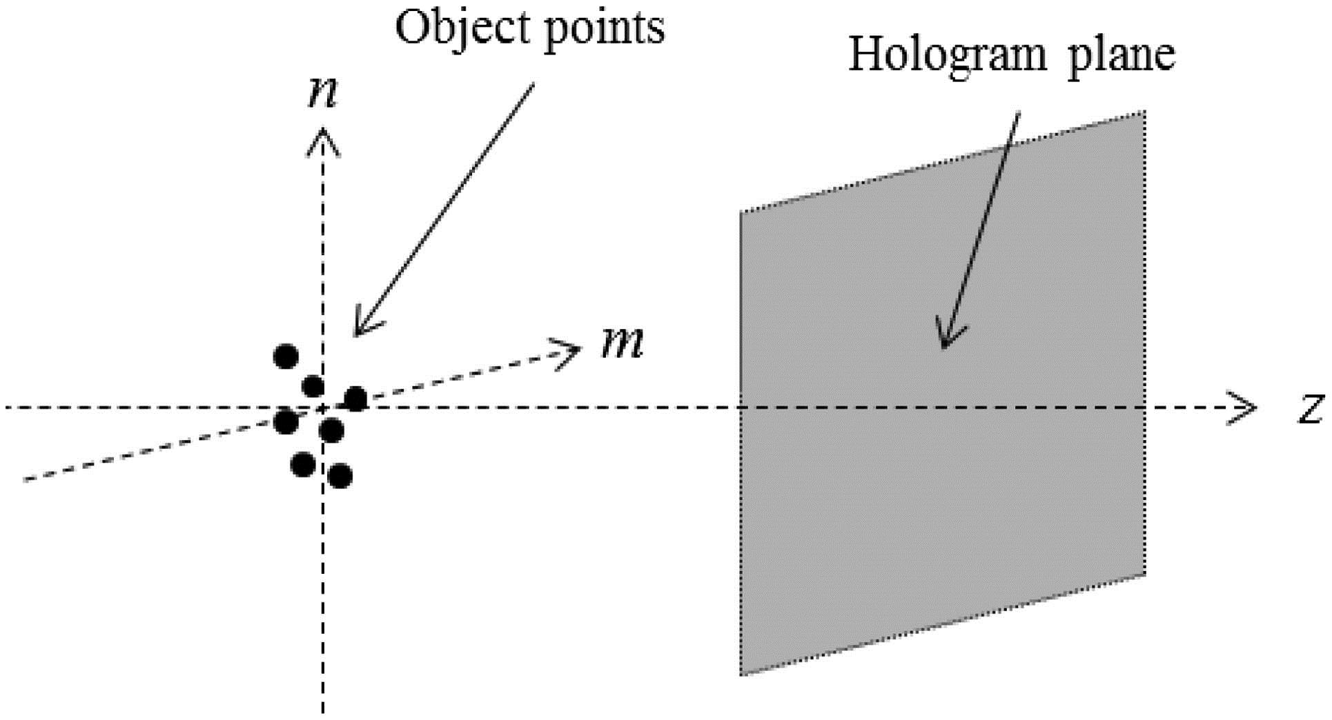
Figure 1.Spatial relation between object points and the hologram plane.
The hologram corresponding to this hypothetic object is simply the summation of the spherical light waves of all the object points on the hologram plane. For a single object point with unit intensity and located at the origin of the object plane, the optical wave it casts on the hologram at an axial distance is given by the spatial impulse response of propagation [14] where is the wavelength of light, is the sampling distance between adjacent pixels on the hologram, , , and . Note that in writing Eq. (1), we have neglected the constant amplitude factor in front of the exponential function. In Eq. (1), it is assumed that the thickness of the object space is small as compared with the separation between the object points and the hologram so that the difference in attenuation of the spherical waves corresponding to the set of object points is negligible. The exponential function on the right-hand side of Eq. (1) is sometimes referred to as the Fresnel zone plate (FZP). For an object with object points, each locating at an axial distance from the hologram, the diffracted wave on the hologram plane can be computed by summing the FZP of individual object points, i.e., where and are the intensity and location of the th object point. We can infer from Eqs. (1) and (2) that the amount of arithmetic operations involved in generating a hologram is rather overwhelming, especially if the number of object points and the size of the hologram are large. Assuming both the horizontal and vertical extents of the hologram and the object space are discretized into columns and rows and have identical pixel size ‘’, the number of operations to compute a hologram pixel is , where is the number of FZPs in the hologram. Each operation is applied to calculate the contribution of an object point to a hologram pixel and is comprised of the arithmetic calculations listed in Table 1. Additions and subtractions are not included, as the computation time is negligible in practice.
| Arithmetic Calculation | Number |
| Multiplication | 2 |
| Square | 3 |
| Square root | 1 |
| Exponential function | 1 |
Table 1. Arithmetic Calculations of a Single Operation for Computing the Hologram with Eq. (2)
If the source object is an image plane with intensity distribution that is parallel to and at a distance from the hologram, Eq. (2) can be represented by the convolution (*) of and as Equation (3), in turn, can be implemented in the frequency space with the Fourier transform. Let and denote the Fourier transform of and , and is the inverse Fourier transform operator, we have For a 3D object, its hologram can be generated with Eq. (4) by decomposing the object into discrete, equally spaced depth planes that are parallel to the hologram, as given by
In software implementation, Eq. (4) can be conducted more swiftly than Eq. (2) if the source object is a single planar image. However, it can be envisaged from Eq. (5) that the computation will become intensive with an increasing number of depth planes. In any case, the time taken to generate a hologram of a 3D object for both approaches is still overwhelming. Although the computation time can be further decreased with special hardware, such as the graphic processing unit (GPU) [15–17], the speed improvement is insufficient to meet the video rate. In the following sections, we shall study some contemporary research works for fast generation of digital holograms.
3. DIRECT LOOK-UP-TABLE METHOD
From Eq. (2) and Table 1, it can be seen that the majority of arithmetic operations are involved in the calculation of the FZP. All of these tedious operations can be discarded if the FZPs for all possible combinations of , , , , and can be pre-computed in advance and stored in the computer memory as a look-up table (LUT). Each entry of the LUT corresponds to value of the function for a particular combination of ; a complex quantity is comprised of a real part and an imaginary part, which are quantized with a certain number of bytes ‘’. A hologram of a 3D object can then be generated by retrieving and summing the pre-stored FZP of each point after being multiplied by its intensity . Ignoring the time taken to retrieve the pre-stored data, which is negligible in practice, the maximum amount of computation in Eq. (2) will be reduced to multiplication operations (i.e., one multiplication operation for a hologram pixel for each object point). The computer memory required for the LUT is , where is the number of depth planes.
Such an approach, which is commonly referred to as the LUT method in CGH, can be traced back to the works of Lucente in the early 1990s [18]. Based on the LUT method, a hologram can be generated swiftly by superimposing the pre-computed fringe patterns of individual points. On the downside, a large amount of computer memory is required to store the pre-computed data. For example, a small square hologram (i.e., ) of the size , representing an object scene of similar dimension, with eight depth planes and (1 byte for each of the real and imaginary parts) will result in an LUT of gigabytes.
4. NOVEL LOOK-UP-TABLE METHOD
To overcome this problem, the novel LUT (N-LUT) method [19] has been developed. The method is shown in Fig. 2 and explained as follows.

Figure 2.Novel look-up-table (N-LUT) method.
From Eq. (2), we can see that the function is a shifted version of along the horizontal and vertical directions. This function is referred to as principal fringe patterns (PFPs), which is the FZP of an object point at the origin of the depth plane at . Instead of pre-computing and storing the FZP for all possible pairings of the object space and hologram locations, it will suffice to store the PFP for different depth planes that are within the range , where is the total number of depth planes. An LUT that is used to store the entire set of PFPs ( to ) is known as the N-LUT. To compute a hologram for a 3D object, the PFP for each object point [e.g., the one located at ] is retrieved from the N-LUT and shifted to the position . The shifted PFP is then multiplied with the intensity of the object point, and the hologram is obtained by summing the shifted PFPs of all the object points. Compared with the LUT method, the number of major arithmetic operations is about the same, i.e., multiplication operations, but the computer memory required to store the N-LUT is reduced to , which is times smaller than that in the LUT. Referring to the previous example, the size of the N-LUT for the hologram is megabytes. Reducing the size of the N-LUT, by taking into account the pixel size and reconstruction distance of the digital hologram, has been conducted and reported in Ref. [20].
5. NOVEL LOOK-UP TABLE WITH RUN-LENGTH CODING METHOD
After the development of the N-LUT method, further enhancement has been conducted and reported in Ref. [21] based on run-length coding. The concept is that physical objects in the real world generally have a smooth geometry. Locally, object points that are usually quite close to each other and rather similar in intensity can be grouped together as a small region with homogeneous properties. As a result, a hologram can be generated on a region wise rather than a pointwise basis, leading to savings in the computation time. In the improved N-LUT method, it is assumed that short horizontal segments each comprised of object points with identical intensity and axial distance to the hologram can approximate a smooth object. An LUT is pre-computed to store the holographic fringe patterns of these horizontal segments. Similar to the PFP in Ref. [19], each segment is centered at the origin of the depth plane on which it resides. The pre-computed fringe patterns of the short segments are known as the N-point PFPs, and the LUT is referred to as an N-point N-LUT. Subsequently, the process of deriving a hologram of a 3D object space with the improved N-LUT method is outlined as follows. Without loss of generality, we have assumed that the object space is a 3D surface represented by the intensity image and the depth map . An N-point N-LUT is pre-computed in advance.
First, the 3D surface is decomposed into horizontal segments, each containing consecutive object points that are identical or very similar in intensity and axial distance (depth) from the hologram. Next, the run-length of each segment is determined, and the corresponding N-point PFP is retrieved from the N-point N-LUT. An example is shown in Fig. 3(a), in which a segment from the 3D surface with ‘’ object points (i.e., run-length is q) is taken to extracted a -point PFP. The retrieved N-point PFP is then shifted to the position of the segment. Finally, a hologram of the 3D surface is generated by summing the N-point PFP of all its segments.
Figure 3.(a) Retrieving an N-point PFP of a segment of the 3D surface. (b) An example showing the partitioning of pixels in the source image into horizontal segments, each having similar properties.
Figure 3(b) depicts an example showing the partitioning of a few horizontal segments of an object image, each of which is comprised of pixels with similar intensity and axial distance from the hologram plane. Each segment is labeled with the variable ‘’. In comparison with the parent N-LUT method [19], the amount of computation involved is reduced as the hologram is computed by accumulating the hologram fringes of groups of object points (i.e., the N-point PFPs) instead of individual ones. Later, the N-LUT method has also been extended to the generation of holograms for 3D video sequence [22,23].
6. LINE SCAN METHOD
The line scan (LS) method was developed by Yang et al. [24] with the aim of reducing the size of the N-LUT. In the N-LUT method, the size of the LUT for the PFP of a single depth plane is . The total size of the N-LUT is equal to the size of a PFP multiplied by the number of depth planes . A PFP is basically an FZP represented by the exponential function in Eq. (1), which is in the form of concentric circular rings centered at the origin. Adopting the polar coordinates, the position of a point at can be denoted by , where and are the radius or the distance of the point to the origin and the azimuth, respectively. Equation (1) can be rewritten in its polar form as From Eq. (6), we observe that the FZP is a function of the radius and independent of the azimuth. In other words, an FZP (or PFP) can be completely defined by any one of its radial lines, which is referred to as a ‘scan line’. If the radial coordinate is discretized into intervals, a small LUT with entries will be sufficient to represent the PFP for a single depth plane. Referring to the previous example, with , the memory required to store the PFPs of a 3D object scene with eight depth planes will be , which is about 1000 times smaller than that required to store the N-LUT.
In computing the hologram, a scan line is retrieved for each object point and used to reconstruct the PFP for . A straightforward implementation is used to compute each point of the PFP as However, it can be inferred from Eq. (8) that each quadrant of the PFP is in fact a mirror image of the others, i.e., and Hence, computation of the PFP from the scan line can be simplified to the computation of the first quadrant of the PFP (), and the remaining quadrants are obtained from the symmetrical relation in Eqs. (8) and (9). The process can be divided into three steps, as illustrated in Fig. 4. In steps 1 and 2, a radial line is generated and expanded into a circular arc covering the first quadrant of the PFP. In step 3, the rest of the quadrants are constructed from the mirror images of the first quadrant.
Figure 4.Line-scan method for generating the PFP.
Expanding a radial line into a circular arc can be implemented with Bresenham’s line algorithm [25]. However, as pointed out in Ref. [26], some of the pixels in the PFP may be missing. Enhancement on the method has been proposed in Ref. [26] and later in Ref. [27].
7. SPLIT LOOK-UP-TABLE FRAMEWORK
Although the N-LUT method has reduced the size of the LUT, the amount of computer memory required to store the pre-computed data is still enormous, in the order of gigabytes. To alleviate this problem, Pan et al. have developed the split LUT (S-LUT) method [28]. Rewriting Eq. (2), we have where , and .
Assuming , , and is an integer multiple of , Eq. (10) can be expressed as where and are the horizontal and the vertical light modulation factors, both of which can be pre-computed in advance and stored in the computer memory. In the generation of the hologram, the pair of functions are fetched from the memory based on values of , , and . As such, the remaining calculations will be the product of the intensity with the pair of retrieved functions for each object point and the summing of the holographic signals for all the object points.
Without loss of generality, we further assume that the pixel size of the object and hologram spaces are identical (i.e., ), and both spaces have horizontal and vertical extents of rows and columns. The size of the LUTs for a single depth plane will be for and for , resulting in an LUT with entries, which is much less than that required in the early LUT method. The size of the S-LUT for multiple planes will be multiplied by the number of depth planes that are used to discretize the 3D object along the axial direction. Referring to a previous example, the memory size of the S-LUT for the hologram is .
Generation of a hologram pixel at location with the S-LUT method is summarized in Fig. 5. The source object point has an intensity and is located at position . The horizontal separation and the vertical separation between the object point and the hologram pixel are computed and taken to retrieve the horizontal and the vertical light modulation factors. Subsequently, the intensity of the object point is multiplied with the pair of light modulator factors to give the hologram pixel.
Figure 5.Computing a hologram pixel with the S-LUT method.
8. COMPRESSED LOOK-UP-TABLE METHOD
The compressed LUT (C–LUT) method [29] is developed by Jia et al. for further reducing the size of the S-LUT. As mentioned before, the total size of the S-LUT for handling a 3D object is equal to the product of the number of depth planes and the number of entries of the S-LUT for a single depth plane. This will lead to the use of a huge amount of computer memory if the number of depth planes is large. This shortcoming is overcome in the C-LUT method. To start with, the spatial impulse response in Eq. (2) is replaced with Eq. (12) based on the finding in Ref. [30] that the reconstructed image of a Fraunhofer hologram is similar to that of a Fresnel hologram. As such, the hologram of a 3D object comprised of P object points can be derived from Fraunhofer diffraction as given by Assuming that the thickness of the 3D object is considerably smaller than the mean distance between the object and the hologram, the above equation can be rewritten as where is the longitudinal light modulation factor, is the horizontal light modulation factor, and is the vertical light modulation factor.
In Eq. (13), only the longitudinal light modulation factor is dependent on the distance of the depth plane. Hence, an LUT, which is referred to as the C-LUT, can be constructed to hold all the combinations of and for different values of and , respectively. Note that both light modulator factors are independent of the depth of the object plane. As such, the overall size of the C-LUT is , which is equivalent to the size of a single depth plane S-LUT. On the downside, the C-LUT method involves the calculation of the longitudinal light modulation factor, which increases the computation loading, as compared with the S-LUT method.
The process of applying the C-LUT method to generate a hologram pixel from an object point is shown in Fig. 6. First, the horizontal and vertical light modulator factors for each object point are fetched from the computer memory. Next, the product of the pair of light modulator factors, together with the depth dependent longitudinal light modulator factor and the intensity of the object point, is computed. The hologram is obtained from the sum of the diffracted waves of all the object points. Subsequent to Ref. [29], further reduction in the size of the C-LUT by two times has been achieved with the accurate C-LUT (AC-LUT) method in Ref. [31].
Figure 6.Computing a hologram pixel with the C-LUT method.
9. WAVEFRONT RECORDING PLANE METHOD
The concept of the wavefront recording plane (WRP), inspired by Yoshikawa et al. [32], is suggested by Shimobaba et al. in Ref. [33]. In simple terms, a WRP can be interpreted as a hologram that is located close to the object space. If the thickness of the object space is small (i.e., all the object points are located at rather similar axial distance from the WRP), each object point will emit a wavefront that is only covering a small FZP on the WRP. A side view of the hologram, the WRP, and three object points is shown in Fig. 7. Each object point is projecting a small FZP on the WRP, and it can be seen that the size of the FZP is proportional to the distance between an object point and the WRP.
Figure 7.Spatial relation between the object space, the WRP, and the hologram plane.
The process of applying the WRP method to generate a hologram can be divided into two major stages, and outlined as follows.
Stage 1: Referring to Fig. 7, each object point is casting a small FZP on the WRP plane that is bounded by a small square support. In other words, the optical wave that is emitted by each object point on the WRP is bounded within the area of its corresponding support. We denote the hologram pattern, and the support of the th object point on the WRP by and respectively. The FZP corresponding to the th object point, which has intensity , is given by where is the distance between the object point and a pixel at on the WRP. The hologram on the WRP is the sum of the FZPs of all the object points as
Stage 2: After the WRP pattern is generated, it is converted into a hologram with the Fresnel diffraction equation given by where is the distance between the WRP and the hologram, and is the free-space impulse response in Fourier optics. As mentioned previously, each support is a small square. Hence, the computation involved in Eqs. (14) and (15) is significantly lower than that required for computing the hologram directly with Eq. (1). With the use of an LUT [34], a hologram representing object points can be generated with the WRP method at around 10 frames per second. To increase the frame rate, the source image can be down-sampled to reduce the number of object points. A fast WRP method, which does not require the use of an LUT, has been demonstrated in Ref. [26]. In this approach, a small FZP of each object point is computed with a fast algorithm, hence, saving the large computer memory that is used in storing the LUT. Another fast method has been proposed in Refs. [35,36], whereby the wavelet transform is employed to reduce the amount of computation. Later, the WRP method has been extended to generate color holograms [37], as well as holograms that are smaller than the object images with the use of shifted Fresnel diffraction [38].
The WRP approach has two major disadvantages. First, in order to speed up the hologram generation process, the number of object points should be reduced. This problem can be alleviated by down-sampling the object scene, resulting in a sparse image of degraded quality. However, if the down-sampling factor is reduced, more object points will be included, and the computation time of hologram generation is increased accordingly. The second problem is that the separation between the WRP must be closed to the object points, so that the support is small for all the object points. This is important for the WRP method, as the computation time, as depicted in Eq. (14), is proportional to the size of the support. In other words, in order to maintain the computation efficiency of the WRP method, the thickness (depth range) of the object must be small. This problem has been addressed with the double WRP [39] and multiple WRP methods [40–42]. In these approaches, the object space is partitioned into two or more narrow zones along the axial direction. A WRP is assigned to each zone to record the diffraction patterns of its constituting object points. The hologram is generated by summing the contributions of the WRPs from all the zones. An alternative WRP method, known as the tilted WRP method [43], is also effective in generating holograms of a deep structure object scene.
In passing, we also note that apart from speeding up the hologram generation process, the WRP framework can also be applied in fast processing of the 3D image represented in a hologram [44], such as image relighting [45] and enhancement [46].
10. INTERPOLATED WAVEFRONT RECORDING PLANE METHOD
As mentioned in section 9, the WRP method faces the dilemma of trading off image quality with the computation efficiency. In view of this, the interpolated WRP (IWRP) method [47] is developed to alleviate this problem. The concept of this method is to generate the diffracted pattern for a small region of points instead of individual ones. The process can be divided into two steps and outlined as follows.
Step 1: The object space and the WRP are first uniformly divided into non-overlapping square blocks of size . For each block in the object space (which is indexed with the variable ‘’), its pixels are assigned the mean amplitude and mean depth values (with reference to the WRP) of its constituting pixels. If , the partition is referred to as a ‘non-empty partition’. An identical area (i.e., same size and at the same horizontal and vertical positions) is partitioned on the WRP plane for each of the square blocks in the object space. The area bounded by the th square block, which is identical for both the object space and the WRP, is referred to as the support and denoted with the symbol . It can be inferred that this mechanism is equivalent to down-sampling and, subsequently, interpolation of the object space. In down-sampling, each partition is reduced to a single sample point carrying the mean amplitude and mean depth value of the object points in it. In interpolation, all of the pixels within the partition are duplicated from the sample point. The diffraction fringe pattern on the WRP corresponding to the th block (i.e., support ) is given by where is the distance between the th object point in and a pixel at location within the support on the WRP. It can be inferred from Eq. (17) that is the hologram of the th square block of pixels in the object space. Similar to the WRP method, an LUT can be constructed to store pre-computed diffraction patterns of the small blocks for different combinations of and .
Step 2: Next, after the hologram fringe patterns of all the non-empty partitions have been derived with Eq. (17), the holographic image on the WRP will be formed by the union of the fringe pattern of the individual partition as where is the number of non-empty partitions. As the WRP now contains the fringe patterns of an interpolated object image, it is renamed as IWRP. With the IWRP approach, the generation of a hologram at 40 frames per second, representing an object scene with four million object points, has been demonstrated in Ref. [47].
11. SUB-LINES AND MULTI-RATE FILTERING
In the generation of a 2D hologram from a 3D object, each hologram pixel is contributed to by all of the pixels in the object scene. Suppose and are the horizontal and vertical extents of the hologram (which are assumed to be identical to that of the object space), respectively, the computational loading is in the order of . The concept of the sub-lines method is to simplify the hologram generation computation into a one-dimensional (1D) process. Inspired by the work on white light digital hologram generation [48], Tsang et al. have extended the concept to the generation of a digital Fresnel hologram [49,50]. The method can be divided into three stages and is outlined as follows.
Stage 1: To begin with, it is assumed that the object points are close together along the longitudinal direction and are located at a mean axial distance from the hologram plane. The object space is sliced into a stack of uniformly spaced horizontal scan planes, as shown in Fig. 8. The process is equivalent to the down-sampled object space by a factor of along the vertical direction with being the separation between adjacent scan planes. For each scan plane, a horizontal sub-line is generated on the hologram plane from the object point(s) residing on it. The vertical position of a sub-line is identical to that of the scan plane. Denoting the index of a scan plane by the symbol (where ), the corresponding sub-line is given by where and are the intensity of the th object point and its axial distance to the hologram plane, respectively. The term is the distance from the th object point to the pixel at horizontal position on the sub-line, and is the total number of object points on the scan plane. It can be envisaged that the sequence of sub-lines is a 2D array that is comprised of discrete horizontal rows of complex-valued pixels.
Figure 8.Partitioning the object into scan planes, each contributing to a sub-line on the hologram plane.
Stage 2: In this stage, the empty space between adjacent sub-lines is interpolated with a low-pass filter (LPF) . A simple implementation of the interpolation filter is a rectangular low-pass function. After applying the LPF, the discrete set of sub-lines will be interpolated to a new array given by Equation (20) can be interpreted as a multi-rate filtering process, as the sizes of and are different. The expression implies interpolation of to so that the missing regions between the sub-lines are filled with the interpolated pixels.
Stage 3: In the third stage, a hologram is generated from the interpolated function . Mathematically, we have where , reminiscent of a 1D version of the free-space impulse response in Fourier optics. From Eqs. (19) to (21), it can be seen that the hologram generation process has been decomposed into three 1D processes, resulting in significant reduction of the computation loading.
The sub-lines method has five major advantages. First, the generation of sub-lines can be realized with simple hardware, such as the field programmable gate array (FPGA). According to Ref. [51], with a commodity FPGA, the throughput of generating the sub-lines is over 108 points per second, enabling a medium size hologram of that can be generated at over 25 frames per second. Second, the data size of the sub-lines that are taken to represent a 3D object scene can be much smaller than the hologram. Third, as a sub-line is a 1D signal, it can be compressed to a one-bit representation with simple delta modulation (DM) [52,53]. Fourth, apart from compressing the sub-lines, it is also feasible to encrypt them as 1D sequences [54] so that at the receiving end the hologram can only be generated and viewed with the correct encryption key. Fifth, the multi-rate interpolation process can also be applied to magnify the size of the object image [55].
12. CONCLUSION
Over the past decade, there are many new research areas in the realm of CGH. A lot of these works are closely related to the development of fast methods and algorithms for hologram generation, which is not unexpected in view of the intensive computation involved in the hologram formation process. Whenever a new method emerges, there is always a question on whether this will be the best and final candidate for CGH. Insofar, it seems that such a unique, ultimate solution for CGH is unlikely to happen. Simply speaking, there are numerous factors that need to be addressed in CGH, e.g., optimizing certain performance measure often leads to jeopardizing others. In this paper, a number of contemporary methods for fast generation of a digital Fresnel hologram have been reported. Many of these methods are partially or fully based on the use of an LUT to replace tedious computing of hologram pixels through direct retrieval of pre-stored values. As we have described in the paper, although all of the computations can indeed be replaced with LUT, the memory required will be beyond the practical limits of even a modern computer. Besides, while the arithmetic operations could be eliminated with a brute-force type of software implementation, the CGH process is neither simplified nor improved.
The overwhelming memory problem in a pure LUT method can be alleviated by trading off the size of the LUT with computation loading. We have described some representative works along this approach, namely, N-LUT, N-LUT with run-length coding, S-LUT, C-LUT, and scan-line methods. It is difficult to say which LUT-based method is better, as each has its own tradeoff between memory usage and computation loading. We have also presented the WRP, IWRP, and sub-line methods, which share the common philosophy of speeding up the computation time through simplification of the hologram formation process. These three methods, however, do not preclude the use of LUT in their implementation and vice versa. In fact, both the WRP and the IWRP methods have incorporated LUTs to enable hologram generation at high frame rates. These favorable outcomes suggested that some kind of synergy could be established between different approaches to further promote the efficiency of CGH in terms of memory usage, computation time, and simplification in the hologram formation process. We anticipate that this paper will provide not only a survey of the current state-of-the-art in CGH but could also inspire new research directions, some of which could emerge through the crossover of existing methods.
References
[1] P. Hariharan. Optical Holography: Principles, Techniques and Applications(1996).
[2] J. P. Waters. Holographic image synthesis utilizing theoretical methods. Appl. Phys. Lett., 9, 405-407(1967).
[3] B. R. Brown, A. W. Lohmann. Complex spatial filtering with binary mask. Appl. Opt., 5, 967-969(1966).
[4] A. W. Lohmann, D. P. Paris. Binary Fraunhofer holograms, generated by computer. Appl. Opt., 6, 1739-1748(1967).
[5] B. R. Brown, A. W. Lohmann. Computer-generated binary holograms. IBM J. Res. Dev., 13, 160-168(1969).
[6] J. J. Burch. A computer algorithm for the synthesis of spatial frequency filters. Proc. IEEE, 55, 599-601(1967).
[7] M. Bayraktar, M. Özcan. Method to calculate the far field of three-dimensional objects for computer-generated holography. Appl. Opt., 49, 4647-4654(2010).
[8] J. Chen, D. Chu. Improved layer-based method for rapid hologram generation and real-time interactive holographic display applications. Opt. Express, 23, 18143-18155(2015).
[9] H. Zhang, L. Cao, G. Jin. Computer-generated hologram with occlusion effect using layer-based processing. Appl. Opt., 56, F138-F143(2017).
[10] Y. Pan, Y. Wang, J. Liu, X. Li, J. Jia. Fast polygon-based method for calculating computer-generated holograms in three-dimensional display. Appl. Opt., 52, A290-A299(2013).
[11] J. Park, S. Kim, H. Yeom, H. Kim, H. Zhang, B. Li, Y. Ji, S. Kim, S. Ko. Continuous shading and its fast update in fully analytic triangular-mesh-based computer generated hologram. Opt. Express, 23, 33893-33901(2015).
[12] H. Nishi, K. Matsushima. Rendering of specular curved objects in polygon-based computer holography. Appl. Opt., 56, F37-F44(2017).
[13] T.-C. Poon, J.-P. Liu. Introduction to Modern Digital Holography with MATLAB(2014).
[14] T.-C. Poon. Optical Scanning Holography with MATLAB(2007).
[15] H. Sato, T. Kakue, Y. Ichihashi, Y. Endo, K. Wakunami, R. Oi, K. Yamamoto, H. Nakayama, T. Shimobaba, T. Ito. Real-time colour hologram generation based on ray-sampling plane with multi-GPU acceleration. Sci. Rep., 8, 1500(2018).
[16] B. Jackin, S. Watanabe, K. Ootsu, T. Ohkawa, T. Yokota, Y. Hayasaki, T. Yatagai, T. Baba. Decomposition method for fast computation of gigapixel-sized Fresnel holograms on a graphics processing unit cluster. Appl. Opt., 57, 3134-3145(2018).
[17] K. Murano, T. Shimobaba, A. Sugiyama, N. Takada, T. Kakue, M. Oikawa, T. Ito. Fast computation of computer-generated hologram using Xeon Phi coprocessor. Comput. Phys. Commun., 185, 2742-2757(2014).
[18] M. Lucente. Interactive computation of holograms using a look-up table. J. Electron. Imaging, 2, 28-34(1993).
[19] S. Kim, E. Kim. Effective generation of digital holograms of three-dimensional objects using a novel look-up table method. Appl. Opt., 47, D55-D62(2008).
[20] S. Kim, J. Kim, E. Kim. Effective reduction of the novel look-up table memory size based on a relationship between the pixel pitch and reconstruction distance of a computer-generated hologram. Appl. Opt., 50, 3375-3382(2011).
[21] S. Kim, E. Kim. Fast computation of hologram patterns of a 3D object using run-length encoding and novel look-up table methods. Appl. Opt., 48, 1030-1041(2009).
[22] S. Kim, X. Dong, M. Kwon, E. Kim. Fast generation of video holograms of three-dimensional moving objects using a motion compensation-based novel look-up table. Opt. Express, 21, 11568-11584(2013).
[23] X. Dong, S. Kim, E. Kim. MPEG-based novel look-up table for rapid generation of video holograms of fast-moving three-dimensional objects. Opt. Express, 22, 8047-8067(2014).
[24] Z. Yang, Q. Fan, Y. Zhang, J. Liu, J. Zhou. A new method for producing computer generated holograms. J. Opt., 14, 095702(2012).
[25] J. Bresenham. A linear algorithm for incremental digital display of circular arcs. Commun. ACM, 20, 100-106(1977).
[26] T. Nishitsuji, T. Shimobaba, T. Kakue, N. Masuda, T. Ito. Fast calculation of computer-generated hologram using the circular symmetry of zone plates. Opt. Express, 20, 27496-27502(2012).
[27] S. Jiao, Z. Zhuang, W. Zou. Fast computer generated hologram calculation with a mini look-up table incorporated with radial symmetric interpolation. Opt. Express, 25, 112-123(2017).
[28] Y. Pan, X. Xu, S. Solanki, X. Liang, R. Tanjung, C. Tan, T. Chong. Fast CGH computation using S-LUT on GPU. Opt. Express, 17, 18543-18555(2009).
[29] J. Jia, Y. Wang, J. Liu, X. Li, Y. Pan, Z. Sun, B. Zhang, Q. Zhao, W. Jiang. Reducing the memory usage for effective computer-generated hologram calculation using compressed look-up table in full-color holographic display. Appl. Opt., 52, 1404-1412(2013).
[30] H. Nakayama, N. Takada, Y. Ichihashi, S. Awazu, T. Shimobaba, N. Masuda, T. Ito. Real-time color electroholography using multiple graphics processing units and multiple high-definition liquid-crystal display panels. Appl. Opt., 49, 5993-5996(2010).
[31] C. Gao, J. Liu, X. Li, G. Xue, J. Jia, Y. Wang. Accurate compressed look up table method for CGH in 3D holographic display. Opt. Express, 23, 33194-33204(2015).
[32] H. Yoshikawa, T. Yamaguchi, R. Kitayama. Real-time generation of full color image hologram with compact distance look-up table. OSA Topical Meeting on Digital Holography and Three-Dimensional Imaging, DWC4(2009).
[33] T. Shimobaba, N. Masuda, T. Ito. Simple and fast calculation algorithm for computer-generated hologram with wavefront recording plane. Opt. Lett., 34, 3133-3135(2009).
[34] T. Shimobaba, H. Nakayama, N. Masuda, T. Ito. Rapid calculation algorithm of Fresnel computer-generated-hologram using look-up table and wavefront-recording plane methods for three-dimensional display. Opt. Express, 18, 19504-19509(2010).
[35] T. Shimobaba, T. Ito. Fast generation of computer-generated holograms using wavelet shrinkage. Opt. Express, 25, 77-87(2017).
[36] D. Arai, T. Shimobaba, T. Nishitsuji, T. Kakue, N. Masuda, T. Ito. An accelerated hologram calculation using the wavefront recording plane method and wavelet transform. Opt. Commun., 393, 107-112(2017).
[37] N. Okada, T. Shimobaba, Y. Ichihashi, R. Oi, K. Yamamoto, T. Kakue, T. Ito. Fast calculation of a computer-generated hologram for RGB and depth images using a wavefront recording plane method. Photon. Lett. Poland, 6, 90-92(2014).
[38] J. Weng, T. Shimobaba, N. Okada, H. Nakayama, M. Oikawa, N. Masuda, T. Ito. Generation of real-time large computer generated hologram using wavefront recording method. Opt. Express, 20, 4018-4023(2012).
[39] A. Phan, M. Piao, S. Gil, N. Kim. Generation speed and reconstructed image quality enhancement of a long-depth object using double wavefront recording planes and a GPU. Appl. Opt., 53, 4817-4824(2014).
[40] A.-H. Phan, M. A. Alam, S.-H. Jeon, J.-H. Lee, N. Kim. Fast hologram generation of long-depth object using multiple wavefront recording planes. Proc. SPIE, 9006, 900612(2014).
[41] A. Symeonidou, D. Blinder, A. Munteanu, P. Schelkens. Computer-generated holograms by multiple wavefront recording plane method with occlusion culling. Opt. Express, 23, 22149-22161(2015).
[42] N. Hasegawa, T. Shimobaba, T. Kakue, T. Ito. Acceleration of hologram generation by optimizing the arrangement of wavefront recording planes. Appl. Opt., 56, A97-A103(2017).
[43] D. Arai, T. Shimobaba, K. Murano, Y. Endo, R. Hirayama, D. Hiyama, T. Kakue, T. Ito. Acceleration of computer-generated holograms using tilted wavefront recording plane method. Opt. Express, 23, 1740-1747(2015).
[44] P. W. M. Tsang, T.-C. Poon. Review on theory and applications of wavefront recording plane framework in generation and processing of digital holograms. Chin. Opt. Lett., 11, 010902(2013).
[45] P. W. M. Tsang, K. Cheung, T.-C. Poon. Real-time relighting of digital holograms based on wavefront recording plane method. Opt. Express, 20, 5962-5967(2012).
[46] P. W. M. Tsang, T.-C. Poon, K. Cheung. Enhancing the pictorial content of digital holograms at 100 frames per second. Opt. Express, 20, 14183-14188(2012).
[47] P. W. M. Tsang, W. Cheung, T.-C. Poon, C. Zhou. Holographic video at 40 frames per second for 4-million object points. Opt. Express, 19, 15205-15211(2011).
[48] T.-C. Poon, H. Yoshikawa. Digital Holography and Three Dimensional Display: Principles and Applications(2006).
[49] P. W. M. Tsang, J.-P. Liu, K. W. K. Cheung, T.-C. Poon. Fast generation of Fresnel holograms based on multirate filtering. Appl. Opt., 48, H23-H30(2009).
[50] P. W. M. Tsang, J.-P. Liu, T.-C. Poon, K. W. K. Cheung. Fast generation of hologram sublines based on field programmable gate array. Holography and Three-Dimensional Imaging, Dwc2(2009).
[51] P. W. M. Tsang, J.-P. Liu, K. W. K. Cheung, T.-C. Poon. An enhanced method for fast generation of hologram sub-lines. Chin. Opt. Lett., 7, 1092-1096(2009).
[52] P. W. M. Tsang, K. W. K. Cheung, T.-C. Poon. Near computation-free compression of Fresnel holograms based on adaptive delta modulation. Opt. Eng., 50, 085802(2011).
[53] P. W. M. Tsang, W. K. Cheung, T. Kim, Y. S. Kim, T.-C. Poon. Low-complexity compression of holograms based on delta modulation. Opt. Commun., 284, 2113-2117(2011).
[54] P. W. M. Tsang, K. W. K. Cheung, T.-C. Poon. Fast numerical generation and hybrid encryption of a computer-generated Fresnel holographic video sequence. Chin. Opt. Lett., 11, 020901(2013).
[55] P. W. M. Tsang, W. C. Situ, W. K. Cheung, T.-C. Poon, C. Zhou. Fast generation of hologram from range camera images based on the sub-lines and holographic interpolation. Proc. SPIE, 8556, 85560R(2012).


