Abstract
In this paper, Er/Yb co-doped fiber amplifiers (EYDFAs) with an Yb-band fiber Bragg grating (FBG) at the pump end to improve the performance of the amplifier is systematically studied. The influence of the reflectivity and center wavelength of the FBG along with the gain-fiber length on the performance of an EYDFA are numericallyanalyzed. The results show that the wavelength of the FBG has critical influence on the efficiency of the EYDFA, whereas the requirement to its reflectivity is relaxed. It is an effective and promising way to improve the efficiency of a high-power pumped EYDFA by introducing a suitable Yb-band FBG at the pump end. Based on the analysis of the underlying principles, suggestions for the practical design and possible further improvement strategies are also proposed.61107035 and 61378043, the National Key Scientific Instrument and Equipment Development Project of China under grant 2013YQ03091502, and the National Basic Research Program of China (973 Program) under grant 2014CB340104.1. INTRODUCTION
In high-power pumped Er/Yb co-doped fiber amplifiers (EYDFAs) and lasers, the Yb-band amplified spontaneous emission (ASE) and the resulting parasitic lasing or self-pulsing has been well-recognized as a main obstacle to their efficiency improving and power scaling [1–3]. In our previous work, we revealed, based on numerical simulations, that the Yb-band ASE can be effectively suppressed by the stimulated amplification and reabsorption of an actively introduced co-pump propagating auxiliary Yb-band signal at proper wavelength [4,5]. In [5], we systematically investigated the influences of the wavelength and power of the auxiliary signal, the fiber length, and the pump power on the efficiency of an EYDFA. The effectiveness of this method has been experimentally well established in several different schemes [6–11]. Recently, we experimentally demonstrated that the same purpose can be accomplished in an improved way by introducing a high-reflection Yb-band fiber Bragg grating (FBG) at the pump-end of an EYDFA to passively autogenerate an appropriate auxiliary signal as the pump power increases to certain extent [12]. Compared with the active scheme, the passive scheme is more compact, cost-effective, and truly compatible with the double-clad gain fibers commonly used in a high-power EYDFA.
In this paper, high-power pumped EYDFAs with an Yb-band FBG at the pump end are numerically optimized. The influence of the center wavelength and reflectivity of the FBG on the performance of an EYDFA is systematically analyzed. The results show that, although the higher the better, the requirement to the reflectivity of the Yb-band FBG is quite lenient. A reflectivity of about 3 dB is usually sufficient. Whereas the center wavelength of the FBG has a crucial influence on the performance of the EYDFA, it not only influences the available power or efficiency of the amplifier but also determines the optimal fiber length and the undesirable residual power of the autogenerated adding signal at the output end of the EYDFA. Furthermore, it can even only have negative influence on the efficiency of the EYDFA if it is not properly selected.
2. NUMERICAL SIMULATION AND ANALYSIS
A diagram of the typical configuration of an EYDFA with a pump-end Yb-band FBG is shown in Fig. 1. The to-be-amplified 1.5 μm band signal can come from a discrete seed source or a pre-stage EYDFA. In the simulations, it is assumed to be a 100 mW continuous wave laser at 1550 nm. High-power laser diodes at or 915 nm are commonly used as the pump to an EYDFA. In either cases, the Yb-ASE problem will eventually occur with the increase of the pump power [4]. To facilitate the comparison with the recently reported experimental results [12], we assume that the pump is at 976 nm with a total power of 16.5 W. For the same reason, the gain fiber is assumed to be the CorActive DCF-EY-10/128. The doping concentrations of and are and , respectively. The cross-relaxation coefficient between Yb and Er ions is (determined by fitting to experimental results). The Yb and Er cross sections of the fiber are shown in Fig. 2. The emission cross sections have been slightly smoothed, based on the manufacturer provided sections [4], by fitting the simulated ASE spectra to the experimentally measured ones. Then, the absorption cross sections are calculated by the McCumber theory [13]. In the simulation, the Yb- and Er-band ASE in the respective spectral ranges of 1000–1100 and 1500–1600 nm are sliced into discrete channels with a wavelength step of 1 nm. The underlying theoretical model and numerical methods have been detailed in our previous work [14].
Sign up for Photonics Research TOC. Get the latest issue of Photonics Research delivered right to you!Sign up now
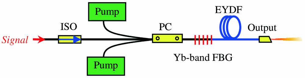
Figure 1.Diagram of an EYDFA with a pump-end Yb-band FBG. ISO, isolator; PC, pump combiner.

Figure 2.Absorption and emission cross sections of Yb and Er ions of the gain fiber.
To investigate the influence of the center wavelength of the FBG () on the performance of an EYDFA, a series of EYDFAs with different ’s in the range from 1000 to 1100 nm with a wavelength interval of 2 nm are simulated. The reflectivity of the FBGs are assumed to be 30 dB. The fiber length is assumed to be 5.6 m. Figure 3(a) shows the simulated results of the power of the amplified signal and the residual power of the FBG reflection as a function of . As a reference, the horizontal dashed lines show the corresponding power if the FBG is not introduced. From Fig. 3(a) we can see that has a crucial influence on the output power or efficiency of the amplifier. When is in the range from to and the range from to , it will have a varying positive and negative impact on the output power, respectively, whereas outside of these ranges, it has no effect on the performance of the amplifier. This phenomenon can be explained by the stimulated amplification and reabsorption of the autogenerated auxiliary signal by the selective reflection of the FBG (labeled as FBG in the subsequent figures). Power evolution of the pump, signal, and FBG reflection of the four featuring configurations (i.e., the best, worst, and two noninfluential ones on each sides) marked with filled balls in different colors in Fig. 3(a) are shown in Fig. 3(b). We can see clearly in Fig. 3(b) that, for the best case, where , an auxiliary signal is generated, effectively amplified, and then gradually well reabsorbed as it passes through the amplifier. Whereas for the worst case, where , although an auxiliary signal is also generated and effectively amplified, it is not effectively reabsorbed. The residual power of the FBG-induced signal is even much higher than that of the signal intended to be amplified. A detailed relationship between the residual power of the FBG-induced signal and is depicted in Fig. 3(a). For the noninfluential cases, as shown in Fig. 3(b), the auxiliary signals are not generated at all because of the low gain at the respective wavelengths. Figures 4(a) and 4(b) show the calculated Yb and Er ASE spectra with , respectively. For comparison, the corresponding ASE spectra of the EYDFA before the FBG is introduced are also shown. In Fig. 4(a), we can see that the dominant backward Yb ASE around is dramatically reduced. Similarly to the active scheme [4], although the forward Yb ASE and the longer wavelength part of the backward Yb ASE are slightly increased, the total Yb ASE power is notably decreased (from to ). In Fig. 4(b) we can see that the introduction of the FBG also slightly influences the Er ASE spectra. For the best case, the output power and the backward Yb ASE spectrum, respectively, shown in Fig. 3(a) and Fig. 4(a) agree well with the experimental results in [12].
Figure 3.(a) Simulated results of the output power of the amplified signal and residual power of the FBG reflection as a function of the center wavelength of the FBG. (b) Power evolutions of the pump, signal, and FBG reflection of the four marked featuring configurations.
Figure 4.(a) Yb and (b) Er ASE spectra of EYDFAs with and without the Yb-band FBG.
Reflectivity is another important parameter of the FBG whose influence needs to be characterized. Figure 5 shows the output power of the EYDFA with as a function of the reflectivity of the FBG. Confirming to our intuition, the higher FBG reflectivity the better. However, from the curve we can conclude that the requirement to the reflectivity is lenient. At a reflectivity of 50% (), the power decrease is less than 1% relative to the nearly 100% reflectivity. Apparently, this will greatly reduce the difficulty in fabricating the FBG, especially in the large-core double-clad fibers commonly required for high-power EYDFAs.
Figure 5.Output power of the EYDFA as a function of the reflectivity of the FBG.
Until now we only optimized the wavelength and reflectivity of the FBG with the length of the gain fiber fixed. In practice, the gain fiber length () is also an important design parameter. Similarly to the active signal aiding scheme [5], the center wavelength of the FBG should have a direct influence on the optimal fiber length (). Figure 6(b) shows the optimal fiber length as a function of . The corresponding power of the amplified signal and the residual power of the FBG reflection are shown in Fig. 6(a). Besides the forward pumping (FP) scheme shown in Fig. 1, simulation results for the backward pumping (BP), in which the pump and signal travels in counter directions in the gain fiber, are also shown in Fig. 6. For the BP scheme, the FBG must also be placed at the pump end. The optimal fiber lengths are determined by a recursive procedure with a step of until (same as the best case in Fig. 2, and marked by green balls in Fig. 6.), where is the output power of the amplified signal. For the FP scheme, comparing Fig. 6(a) to Fig. 3(a), we can see that, with the length of the gain fiber optimized, the positive range of is expanded by squeezing the negative range. In Fig. 6, we can see that the optimal combination is [, ] at the given pump power. This sets an upper boundary to (the vertical dashed line shown in Fig. 6). Because with a longer , not only the maximum achievable signal power decreases, but also the residual power of the FBG reflection increases even though with a longer gain fiber. Thus, in practice, combinations to the near left of the boundary ought to be selected. When cost effectiveness is taken into account, the optimal combinations may not be the best. For example, with the combination of [, ], the output power is only lower than that of the optimal combination, but the optimal fiber length is 2.6 m shorter. Furthermore, for high-power amplifiers, a longer gain fiber length may cause other problems, such as the stimulated Brillouin scattering (SBS) if the linewidth of the signal is narrow. Results of the BP scheme show that the proposed method is also effective for a counterpumping scheme and follows the similar trend. Because the efficiency is higher and the optimal fiber length is slightly shorter than that of the FP case, this scheme is superior if the accompanying complexity in isolation and low-loss connection at the signal input end can be solved.
Figure 6.(a) Output power of the amplified signal and residual power of the FBG reflection of EYDFAs with (b) optimal gain fiber lengths as a function of the center wavelength of the FBG.
3. DISCUSSION AND CONCLUSION
Whether the aiding Yb-band signal is actively introduced by a standalone laser [6,10] or passively generated by an FBG [12], the underlying principle that helps to improve the efficiency of a high-power EYDFA is the same, i.e., the stimulated amplification and reabsorption of the aiding signal. These two processes are determined by the emission and absorption cross sections of the Yb ions of the gain fiber, which are ultimately affected by the composition of the fiber material. All works until now have been based on commercially available EYDFs. Optimizing the composition of the gain fiber may be an effective way to make the best out of the method.
Although the method has been proved to be effective both theoretically and experimentally, it does have one defect: the length of the gain fiber has to be lengthened to reabsorb the excessive energy taken back by the amplified aiding signal. Beside the disadvantages such as SBS mentioned above, a longer required fiber length will, to some extent, depress the benefit of using an EYDF as the gain fiber, i.e., increasing the pump absorption coefficient and making the amplifier more compact. A possible solution to this dilemma is to introduce an Yb-band high Q-factor cavity into an EYDFA with a pair of high-reflection FBGs at proper wavelength. Limited by the end-pumping (or longitudinal pumping) scheme, a high gain in both of the Yb and Er bands are mainly focused near the pump end. Whereas in the latter part of the gain fiber, the population density of the upper level of and are much lower. As shown in Fig. 3(b), in the latter part of the fiber, the amplified auxiliary signal serves as the actual pump. Thus, introducing another high-reflective Yb-band FBG at the output end to form a high- cavity should be helpful to reduce the optimal fiber length. Because the FBG can be inscribed on a compatible double-clad fiber, this solution is also suitable to high-power EYDFAs based on double-clad EYDFs. This nested resonator–amplifier configuration, in which an Yb-band high- resonator and an Er-band amplifier is sharing the same fiber, if assisted by concentration optimization of the gain fiber, is potentially a good way to improve the performance of EYDFAs. This idea can even possibly be extended to a nested multiple-resonator configuration for amplifiers or lasers based on other double or triple rare-earth ions co-doped fibers, e.g., Yb/Tm or Yb/Er/Tm co-doped fibers [15,16].
In summary, EYDFAs with an Yb-band FBG at the pump end have been systematically characterized according to the center wavelength and reflectivity of the FBG, and the length of the gain fiber. Design considerations also have been discussed. The results show that the wavelength of the FBG has a critical influence on the efficiency of the EYDFA, whereas the requirement to its reflectivity is further relaxed. It is a simple and effective way to improve the efficiency of a high-power pumped EYDFA by introducing a suitable Yb-band FBG at the pump end.
ACKNOWLEDGMENT
Acknowledgment. This work is partially supported by the Natural Science Foundation of Tianjin under grant 13JCYBJC16100, the National Natural Science Foundation of China under grants 61107035 and 61378043, the National Key Scientific Instrument and Equipment Development Project of China under grant 2013YQ03091502, and the National Basic Research Program of China (973 Program) under grant 2014CB340104.
References
[1] J. Yoonchan, Y. Seongwoo, C. A. Coderaard, J. Nilsson, J. K. Sahu, D. N. Payne, R. Horley, P. W. Turner, L. Hickey, A. Harker, M. Lovelady, A. Piper. Erbium:Ytterbium codoped large-core fiber laser with 297-W continuous-wave output power. IEEE J. Sel. Top. Quantum Electron., 13, 573-579(2007).
[2] J. K. Sahu, Y. Jeong, D. J. Richardson, J. Nilsson. A 103 W erbium-ytterbium co-doped large-core fiber laser. Opt. Commun., 227, 159-163(2003).
[3] V. Kuhn, P. Weßels, J. Neumann, D. Kracht. Stabilization and power scaling of cladding pumped Er:Yb-codoped fiber amplifier via auxiliary signal at 1064 nm. Opt. Express, 17, 18304-18311(2009).
[4] Q. Han, J. Ning, Z. Sheng. Numerical investigation of the ASE and power scaling of cladding-pumped Er-Yb codoped fiber amplifiers. IEEE J. Quantum Electron., 46, 1535-1541(2010).
[5] Q. Han, Y. He, Z. Sheng, W. Zhang, J. Ning, H. Xiao. Numerical characterization of Yb-signal-aided cladding-pumped Er:Yb codoped fiber amplifiers. Opt. Lett., 36, 1599-1601(2011).
[6] V. Kuhn, D. Kracht, J. Neumann, P. Weßels. Dependence of Er:Yb-codoped 1.5 μm amplifier on wavelength-tuned auxiliary seed signal at 1 μm wavelength. Opt. Lett., 35, 4105-4107(2010).
[7] G. Sobon, P. Kaczmarek, A. Antonczak, J. Sotor, K. M. Abramski. Controlling the 1 μm spontaneous emission in Er/Yb co-doped fiber amplifiers. Opt. Express, 19, 19104-19113(2011).
[8] G. Sobon, P. Kaczmarek, K. M. Abramski. Erbium-ytterbium co-doped fiber amplifier operating at 1550 nm with stimulated lasing at 1064 nm. Opt. Commun., 285, 1929-1933(2012).
[9] G. Sobon, D. Sliwinska, P. Kaczmarek, K. M. Abramski. Er/Yb co-doped fiber amplifier with wavelength-tuned Yb-band ring resonator. Opt. Commun., 285, 3816-3819(2012).
[10] D. Sliwinska, P. Kaczmarek, G. Sobon, K. M. Abramski. Double-seeding of Er/Yb Co-doped fiber amplifiers for controlling of Yb-ASE. J. Lightwave Technol., 31, 3381-3386(2013).
[11] M. Steinke, A. Croteau, C. Paré, H. Zheng, P. Laperle, A. Proulx, J. Neumann, D. Kracht, P. Wessels. Co-seeded Er3+:Yb3+ single frequency fiber amplifier with 60 W output power and over 90% TEM00 content. Opt. Express, 22, 16722-16730(2014).
[12] Q. Han, Y. Yao, Y. Chen, F. Liu, T. Liu, H. Xiao. Highly efficient Er/Yb-codoped fiber amplifier with an Yb-band fiber Bragg grating. Opt. Lett., 40, 2634-2636(2015).
[13] D. E. McCumber. Einstein relations connecting broadband emission and absorption spectra. Phys. Rev., 136, A954-A957(1964).
[14] Q. Han, T. Liu, X. Lü, K. Ren. Numerical methods for high-power Er/Yb-codoped fiber amplifiers. Opt. Quantum Electron., 47, 2199-2212(2015).
[15] N. Saidin, S. W. Harun, H. Ahmad, S. M. M. Ali, S. S. A. Damanhuri, A. Halder, M. C. Paul, S. Das, M. Pal, S. K. Bhadra. Enhancement of Thulium-Ytterbium doped fiber laser efficiency using dual-pumping method. Microwave Opt. Technol. Lett., 57, 285-287(2015).
[16] A. Pal, A. Dhar, S. Das, S. Y. Chen, T. Sun, R. Sen, K. T. V. Grattan. Ytterbium-sensitized Thulium-doped fiber laser in the near-IR with 980 nm pumping. Opt. Express, 18, 5068-5074(2010).


