1School of Physics and Optoelectronic Engineering, Xidian University, Xi’an 710071, China
2National Engineering Laboratory for Destructive Testing and Optoelectronic Sensing Technology and Application, Nanchang Hangkong University, Nanchang 330063, China
3School of Electrical Engineering & Intelligentization, Dongguan University of Technology, Dongguan 523808, China
Zheyu Wu, Bin Liu, Jiangfeng Zhu, Juan Liu, Shengpeng Wan, Tao Wu, Jinghua Sun, "Asymmetrical tapered SMS fiber coupler for simultaneous measurement of temperature and refractive index and its application for biosensing," Chin. Opt. Lett. 18, 061201 (2020)
Copy Citation Text
An asymmetrical tapered singlemode–multimode–singlemode (SMS) fiber coupler based on two parallel physical contact SMS fiber structures was proposed. Since the coupler includes modes both from fiber core and cladding, two dips of the transmission spectrum exhibit different sensing characteristics to the surrounding temperature and refractive index (RI) change, which allows the use of the standard matrix inversion method to determine temperature and RI simultaneously. The temperature sensitivities of 0.0498 and 0.0324 nm/°C and RI sensitivities of 1151.76 and 1325.66 nm/RIU have been achieved, respectively. For biosensing application, with the functionalized fiber coupler sensor, a human chorionic gonadotropin concentration of 0.05 mIU/mL has been detected for a wavelength shift of 0.2 nm with good stability and excellent selectivity. The developed tapered SMS fiber coupler structure has advantages of simultaneous measurement of two independent parameters, simple configuration, low cost, and good repeatability that offer a great potential for medical diagnostics.
Fiber optic sensors are particularly attractive for deployment in harsh environments, such as high temperature, high pressure, corrosive, and high-voltage conditions due to their compact size, high stability, insusceptibility to electromagnetic interference, and chemical and mechanical robustness[1]. They have been used in a wide range of sensing applications to measure physical properties such as refractive index (RI), temperature, strain, and humidity through various sensor structure designs[2–6]. Cross sensitivity is a general issue for most of optical fiber sensors; for example, for an RI optical sensor, it will also be sensitive to temperature. If the measurement of RI is not in a controlled temperature environment, which is most cases in reality, additional measurement of temperature is required. It is, thus, important to realize simultaneous measurement of multiple parameters in a single measurement. There are different types of optical fiber sensors that have been studied for simultaneous measurement of multiple parameters, such as a singlemode-no-core-hollow-core-no-core-singlemode (SNHNS) structure[7], a P-D fiber structure-based Sagnac loop sensor[8], an optical microfiber coupler (OMC) combined with a polarization maintaining fiber (PMF)[9], a fiber-based Mach–Zehnder interferometer (MZI)[10–14], and a Fabry–Perot (FP) cavity and fiber Bragg grating (FBG) cascaded optical fiber[15]. These sensors suffer disadvantage of either low sensitivity or poor stability.
On the other hand, recently a fiber-to-fiber coupling technique based on evanescent field coupling between two parallel fibers has been proposed and investigated[16–24]. The light coupling between two parallel long-period gratings (LPGs) is mainly used as wavelength-selective bandpass filters or multiplexers[16–19]. Optical coupling between a long-period fiber grating and a parallel tilted FBG (TFBG) was experimentally demonstrated and achieved a peak coupling efficiency of ∼80% at ∼1534 nm[20]. Due to TFBGs-based refractometers effectively coupling the fundamental core mode to fiber cladding and generating strong evanescent fields, the coupled optical fiber refractometer based on a TFBG and a D-shaped fiber or an in-fiber mirror can be applied to a wide range of RI measurements[21,22]. Among these techniques, optical couplers based on the singlemode–multimode–singlemode (SMS) configuration have unique advantages of low cost and ease of fabrication[23,24].
It is well known that the tapered fiber is sensitive to surrounding RI change. For example, Wang et al. reported a tapered multimode-fiber-based sensor, which offers a maximum sensitivity of 1913 nm/RIU[25]. A compact fiber-optic sensor based on an over-coupled tapered fiber coupler exhibiting a sensitivity of 2171 nm/RIU maintains a linear response in a large range of RI[26]. An RI sensor based on a wet-etched fused fiber coupler demonstrated that etched fused fiber couplers with reduced waist size had high sensitivity to the RI of an external medium, which was 1125 nm/RIU[27]. RI sensors based on tapered fiber couplers with a Sagnac loop achieved maximum sensitivity of 3617 nm/RIU for measuring the RI ranging from 1.33 to 1.41[28]. The change in RI caused by the interaction of biomolecules on the surface of the coupler was detected as a change in transmission power; this sensor allows the construction of a low-cost, portable, and label-free biosensing system[29]. Compared with the reported sensors, our optical couplers based on SMS configuration have higher RI sensitivity and are more stable.
Sign up for Chinese Optics Letters TOC. Get the latest issue of Chinese Optics Letters delivered right to you!Sign up now
In this Letter, a novel asymmetrical tapered SMS fiber coupler was proposed and investigated for simultaneous temperature and RI measurement based on two parallel physical contact SMS fiber structures. By tapering the parallel placed structures into a diameter less than 10 μm, the sensor has very high RI sensitivity. Since the tapered coupler structure is composed of two fibers, its taper diameter is larger than that of a single tapered fiber, and the sensor is more stable. By properly functionalizing the tapered SMS fiber coupler, the sensor can be used for highly sensitive biosensing application, where human chorionic gonadotropin (hCG) detection was demonstrated as an example.
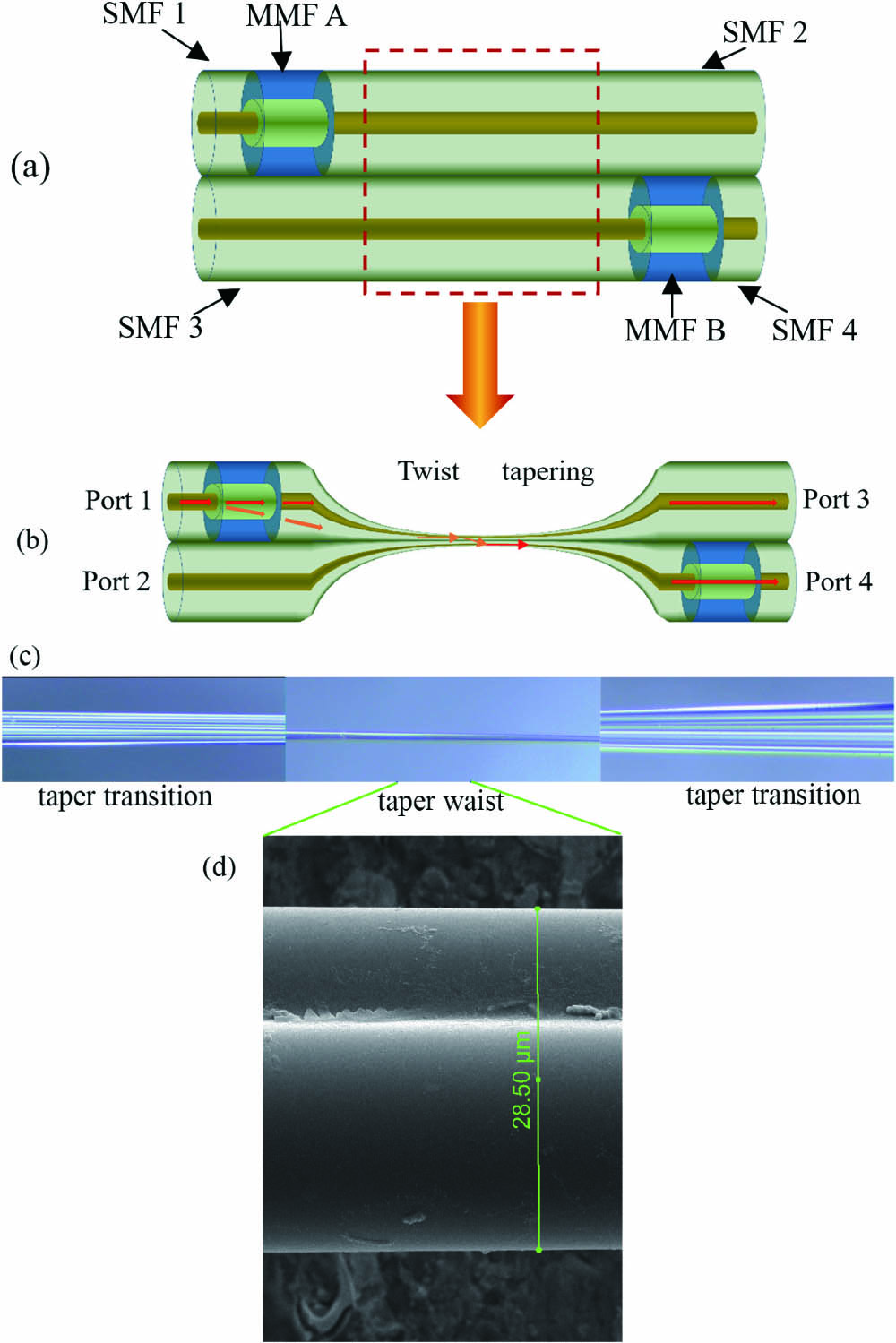
As reported by Wu et al. in 2012[23], if two SMS fiber structures are placed parallel in physical contact, coupling will occur between two SMS structures, as shown in Fig. 1(a). When the light is injected from the input singlemode fiber (SMF) 1 into the multimode fiber (MMF) A, multiple modes will be excited, and there will be interference within the MMF A section in the SMS 1 fiber structure. When the light is coupled again to the output SMF 2, both core and cladding modes will be excited and propagate within SMF 2. The cladding modes with SMF 2 will be coupled to the input SMF 3 in SMS 2, which will enter the fiber core of MMF B and in turn will excite a guided core mode in SMF 4, and, hence, the coupled light will be transmitted to port 4. If the coupling section is tapered to micro size, the structure has potential for a highly sensitive RI sensor and for multiple parameters measurement. A schematic diagram of the proposed tapered SMS coupler is shown in Fig. 1(b). Figure 1(c) shows a microscopic enlarged view of the taper transition and taper waist area. The scanning electron microscope (SEM) image of the taper waist area in Fig. 1(d) shows an obvious coupler structure. The SMF coupling section has been tapered to a small diameter, which has a much larger evanescent field to interact with the surrounding material and, hence, higher sensitivity. In our experiment, the length of the taper region is 3 cm, and the length of the MMF is 1 cm.
Figure 1.Schematic diagram of (a) conventional SMS coupler and (b) tapered SMS coupler; (c) the photomicrograph of the taper transition and taper waist area; (d) the SEM image of the taper waist area.
Assume that the modes of propagation in the SMF include the core and cladding modes, and the amplitudes are and , respectively. MMF A and B are the same type with the length of ; then, after a propagation distance within MMF A, the field can be written as[20]where is the total number of modes propagating within MMFs A and B, is the excitation coefficient for each mode, is the field distribution within the MMF corresponding to the eigenmode, and is the propagation constant of the eigenmode within the MMF.
According to the above analysis, the core modes transmitted within MMF B will excite the guided core mode in SMF 4. The amplitude of the core mode within SMF 4 can thus be expressed as where is the length of the coupling region, is the cladding modes in SMF 3, which will be coupled to core modes propagating within MMF B, and is the eigenmode of SMF 1, which is the input to MMF A.
Based on the above structure design, the tapered SMS coupler was firstly fabricated. The MMF used in our experiments has core and cladding diameters of 50 and 125 μm, respectively, and a length of 1 cm. Two SMS structures were placed parallel and aligned with a separation distance of 3 cm (end of MMF A and start of MMF B). The two SMS structures were then twisted and tapered using a commercial fiber tapering system (OC-2010, JILONG) by heating and pulling the coupling SMF section [dashed red rectangle section in Fig. 1(a)]. The taper waist diameter of the coupler is 7 μm, which was used for further experiments.
An RI sensitivity test of the tapered SMS coupler with a 7 μm taper waist diameter has been carried out in three RI ranges of 1.33, 1.37, and 1.42 by immersing the sensor into a container containing a mixture of dimethyl sulfoxide and deionized water, where different ratios of the mixture correspond to different RIs. The measurement results are shown in Figs. 2(a)–2(c). The RI sensitivities of the sensor with the 7 μm taper waist diameter are 1151.76, 3850.90, and 17,360.40 nm/RIU for the RI ranges around 1.33, 1.37, and 1.42, respectively, demonstrating ultrahigh RI response of this structure.
Figure 2.Experimentally observed RI sensitivity of the tapered SMS coupler in different RI ranges: (a) 1.33, (b) 1.37, and (c) 1.42.
At the coupling section of the fiber sensor, there are both core and cladding modes, which have different responses to the surrounding temperature and RI and, hence, have the potential for multiple parameters’ measurement. For example, the interference between these modes will generate multiple transmission dips in the output spectra of the tapered SMS coupler, as shown in Fig. 3, where two dips (dip-1 and dip-2) were observed. Measurements were firstly carried out by fixing the sensor and surrounding RI liquid at a fixed temperature (circa 30°C), and we measured the wavelength shifts of the two dips at different surrounding RIs, varying from 1.3320 to 1.3381. The transmission spectrum of the sensor at different RIs is shown in Fig. 4(a). At a fixed temperature, as RI increases, the wavelength of both dip-1 and dip-2 shifts to longer wavelengths monotonically but with different shift rates. Figure 4(b) summarized the corresponding wavelength shifts versus RI, and the RI sensitivities for dip-1 and dip-2 are 1151.76 nm/RIU and 1325.66 nm/RIU, respectively.
The temperature dependence of the sensor was investigated by putting the SMS coupler into air, so the wavelengths of dip-1 and dip-2 are different from those of the above results. By varying the surrounding temperature from 30°C to 70°C and recording spectra with temperature intervals of 5°C, the spectral responses of dip-1 and dip-2 at different temperatures are shown in Figs. 5(a) and 5(b), respectively. Figure 5(c) shows the summarized wavelength shifts of dip-1 and dip-2 versus temperature. Both dip-1 and dip-2 undergo a monotonical red wavelength shift as the temperature increases, and the temperature sensitivities of dip-1 and dip-2 are 0.0498 nm/°C and 0.0324 nm/°C, respectively. It is reasonable to assume that both temperature and RI variations will lead to wavelength shifts of dip-1 and dip-2, which can be expressed by the following matrix[30–32]: where and are the wavelength shift of dip-1 and dip-2 induced by both temperature and RI variations of and , respectively. and are the temperature sensitivity of dip-1 and dip-2, and and are the temperature sensitivity of dip-1 and dip-2, respectively. By utilizing the matrix inversion methods, we can get the following matrix: Hence, by measuring the wavelength shifts of dip-1 and dip-2, the variation of temperature and RI can be determined. By substituting the measured sensitivity in Figs. 4(b) and 5(c) into Eq. (2), both temperature and RI variations can be calculated by
Figure 5.(a) Spectral response of dip-1 at different temperatures; (b) spectral response of dip-2 at different temperatures; (c) wavelength shift versus temperature for dip-1 and dip-2.
The feasibility of the tapered SMS coupler for biosensing was investigated by functionalizing the sensor with the following steps: treat the fiber sensor using silylating reagent (5% in ethanol) for about 2 h in a glass channel; wash the fiber sensor with ethanol and phosphate buffer () three times; treat the fiber sensor with freshly prepared activation solution for 1 h (0.8 mg/mL EDC, 1.2 mg/mL NHSS in phosphate buffer); wash the fiber sensor with phosphate buffer three times; treat the fiber sensor with capture antibody solution [anti-hCG-β, 15 μg/mL diluted by phosphate buffer saline (PBS) buffer ] for 4 h in a new glass channel; remove the capture antibody solution and then treat the fiber sensor with 1% bovine serum albumin (BSA, in PBS) for 2 h to block nonspecific binding; wash the fiber sensor with PBS buffer at least three times.
The functionalization process is illustrated in Fig. 6. The sensor was then used for hCG detection experiments. In the experiment, since the PBS buffer was used for diluting and washing hCG in the whole process, the stability for the sensor structure immersed in PBS was firstly tested. As shown in Fig. 7, three rounds of stability rests have been carried out. The wavelength shift is stable and repeatable with an average wavelength change of over 30 min duration.
Figure 6.(a) Surface modification and Ab immobilization procedure; (b) zoomed fiber waist region showing RI change caused by the bonding of hCG on the fiber surface, immobilized with hCG-β Ab; (c) functionalized fiber sensor for hCG detection.
The sensor was then utilized to detect hCG samples with different concentrations of 0.05, 0.5, 5, 50, and 500 mIU/mL, respectively. Figures 8(a)–8(c) show the output spectral responses of the sensor immersed in three different concentrations (0.05, 5, and 500 mIU/mL) of hCG, respectively. Due to the specific binding between hCG and the functionalized fiber sensor, the wavelength dip in the transmission spectrum shifts towards a longer wavelength monotonically as the time of immersion increases. The spectral dip is mainly shifted within the initial 5 min, after which the spectral shift slows down and tends to be stable after 20 min. As the hCG concentration is higher, the spectral dip shift is larger.
Figure 9.Summary of captured Ab concentration on the capability of the fiber surface to detect hCG in the entire sample range from 0.05 to 500 mIU/mL.
Figures 9(a) and 9(b) summarize the wavelength shift over time for the functionalized sensor at five different concentrations of hCG samples (0.05, 0.5, 5, 50, and 500 mIU/mL). The results show the sensor has good repeatability. At concentrations of 0.05, 0.5, 5, 50, and 500 mIU/mL, the average wavelength shift is , , , , and , respectively. A nonlinear fitting is achieved as described:
To test selectivity of the proposed sensor, high concentrations of Escherichia coli () and Staphylococcus aureus () were introduced separately to the functionalized fiber sensor. As seen in Fig. 10, there is no significant wavelength shift (), which is slightly larger than in PBS and much less than in hCG. So, the functionalized fiber sensor has very good selectivity for detection of hCG.
Figure 10.Selectivity test for the sensor by immersing into a solution of Escherichia coli () and Staphylococcus aureus ().
In conclusion, a novel asymmetrical tapered SMS fiber coupler for simultaneous measurement of temperature and RI and its biological detection for hCG has been proposed and investigated. Since the coupler includes modes both from the fiber core and cladding, two dips of the transmission spectrum exhibit different sensing responses to the surrounding temperature and RI. The temperature sensitivities of 0.0498 and 0.0324 nm/°C and RI sensitivities of 1151.76 and 1325.66 nm/RIU have been achieved, respectively. By constructing a coefficient matrix utilizing different temperature and RI responses of the two dips, simultaneous measurement of temperature and RI can be realized. The proposed fiber coupler sensor was functionalized for biosensing applications. An hCG concentration of 0.05 mIU/mL has been detected for a wavelength shift of 0.2 nm with good stability and excellent selectivity. The proposed tapered SMS fiber coupler structure has the advantage of simple fabrication, low cost, and good repeatability and will have bright prospects for applications in fiber sensing, such as medical diagnostics and biological detection.
Zheyu Wu, Bin Liu, Jiangfeng Zhu, Juan Liu, Shengpeng Wan, Tao Wu, Jinghua Sun, "Asymmetrical tapered SMS fiber coupler for simultaneous measurement of temperature and refractive index and its application for biosensing," Chin. Opt. Lett. 18, 061201 (2020)