• Chinese Optics Letters
  • Vol. 16, Issue 4, 041001 (2018)
Xunbo Yu*, Xinzhu Sang, Xin Gao, Shenwu Yang, Boyang Liu, Duo Chen, Binbin Yan, and Chongxiu Yu
Author Affiliations
  • State Key Laboratory of Information Photonics and Optical Communications, Beijing University of Posts and Telecommunications, Beijing 100876, China
  • show less
    DOI: 10.3788/COL201816.041001 Cite this Article Set citation alerts
    Xunbo Yu, Xinzhu Sang, Xin Gao, Shenwu Yang, Boyang Liu, Duo Chen, Binbin Yan, Chongxiu Yu. Distortion correction for the elemental images of integral imaging by introducing the directional diffuser[J]. Chinese Optics Letters, 2018, 16(4): 041001 Copy Citation Text show less
    Schematics of (a) the traditional II and (b) the separated optical system.
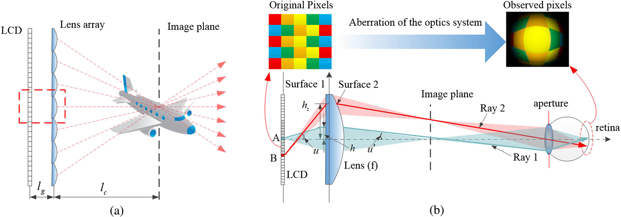
    Fig. 1. Schematics of (a) the traditional II and (b) the separated optical system.
    Reconstructed 3D image of the integral imaging. The distances between the reconstructed images and lens array are (a) 30, (b) 60, (c) 90, and (d) 120 mm.
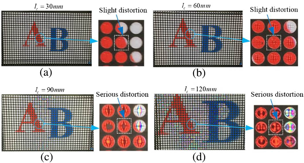
    Fig. 2. Reconstructed 3D image of the integral imaging. The distances between the reconstructed images and lens array are (a) 30, (b) 60, (c) 90, and (d) 120 mm.
    Distortion grid maps of the separated optical system. The distances between the reconstructed images and lens array are (a) 30, (b) 60, (c) 90, and (d) 120 mm.
    Fig. 3. Distortion grid maps of the separated optical system. The distances between the reconstructed images and lens array are (a) 30, (b) 60, (c) 90, and (d) 120 mm.
    Schematics of (a) the improved traditional II and (b) the separated optical system with the directional diffuser.
    Fig. 4. Schematics of (a) the improved traditional II and (b) the separated optical system with the directional diffuser.
    Reconstructed 3D image of the II system with the directional diffuser. The distances between the reconstructed images and lens array are (a) 30, (b) 60, (c) 90, and (d) 120 mm.
    Fig. 5. Reconstructed 3D image of the II system with the directional diffuser. The distances between the reconstructed images and lens array are (a) 30, (b) 60, (c) 90, and (d) 120 mm.
    Distortion grid maps of the separated optical system with the directional diffuser. The distances between the reconstructed images and lens array are (a) 30, (b) 60, (c) 90, and (d) 120 mm.
    Fig. 6. Distortion grid maps of the separated optical system with the directional diffuser. The distances between the reconstructed images and lens array are (a) 30, (b) 60, (c) 90, and (d) 120 mm.
    Diagram of the numerical value of distortion.
    Fig. 7. Diagram of the numerical value of distortion.
    Schematic of the proposed floating 3D display system.
    Fig. 8. Schematic of the proposed floating 3D display system.
    Photographs of reconstructed images at different depth layers.
    Fig. 9. Photographs of reconstructed images at different depth layers.
    Photographs taken at different viewing angles (see Visualization 1).
    Fig. 10. Photographs taken at different viewing angles (see Visualization 1).
    Xunbo Yu, Xinzhu Sang, Xin Gao, Shenwu Yang, Boyang Liu, Duo Chen, Binbin Yan, Chongxiu Yu. Distortion correction for the elemental images of integral imaging by introducing the directional diffuser[J]. Chinese Optics Letters, 2018, 16(4): 041001
    Download Citation