
Lin Chen, Huihui Li, Weiming Hao, Xiang Yin, Jian Wang. Hyperbolic metamaterials for high-efficiency generation of circularly polarized Airy beams[J]. Chinese Physics B, 2020, 29(8):
- Chinese Physics B
- Vol. 29, Issue 8, (2020)
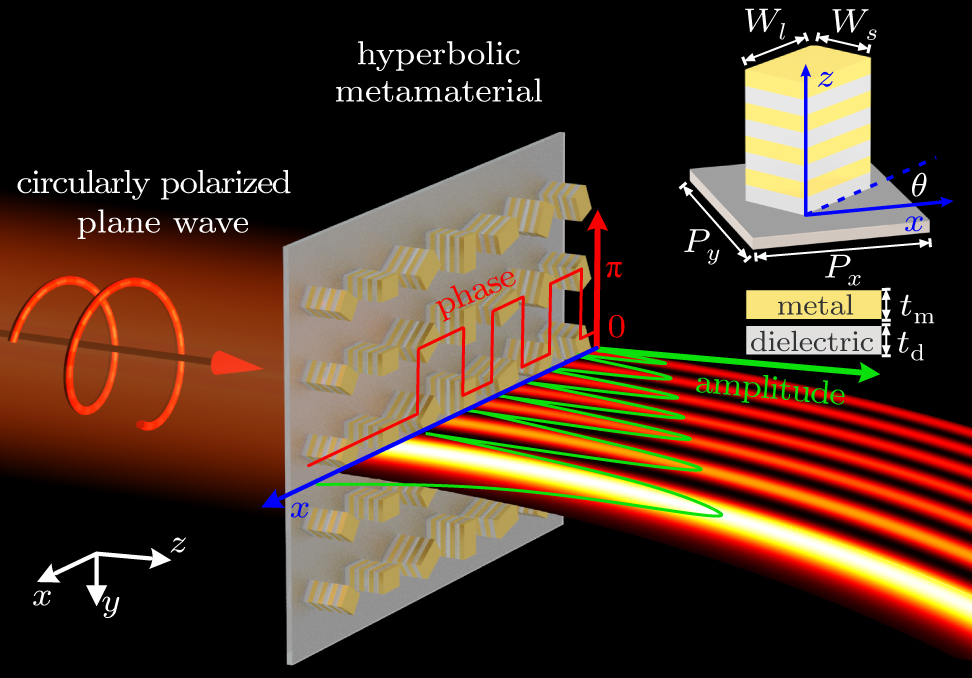
Fig. 1. Schematic diagram of an HMM Airy beam generator, where the HMM meta-atom is presented in the top right corner. The thicknesses of the metal and dielectric layers are denoted by t m and t d, respectively. The widths of long- and short-edges of HMM are denoted by Wl and Ws , respectively. The angle between the l axis and the x axis is the orientation angle θ . LCP plane waves normally illuminate the HMM Airy beam generator from the left-hand side.
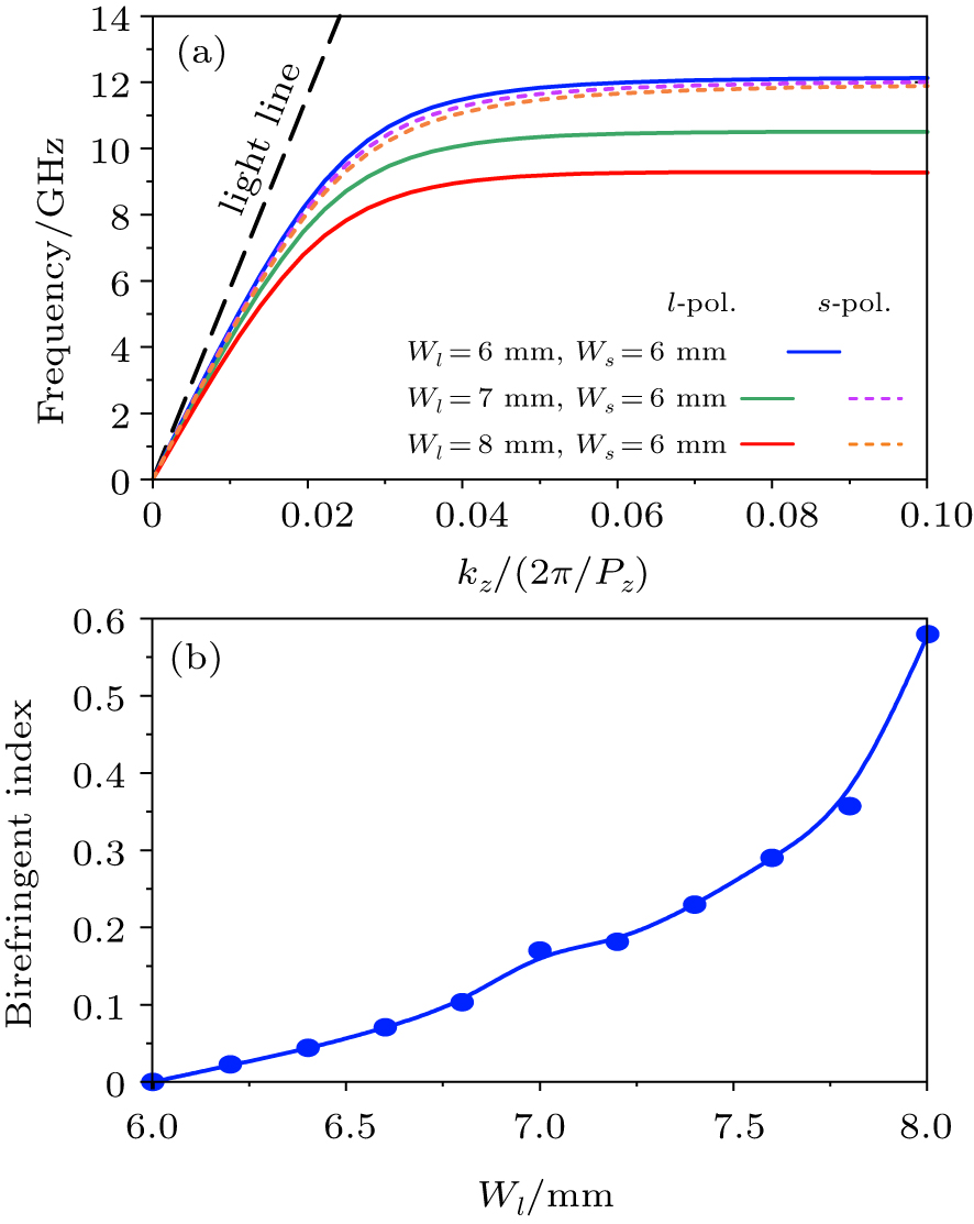
Fig. 2. (a) The dispersion relations of l - and s -polarized fundamental SW modes for RHMM with different Wl . (b) The birefringent index between l - and s -polarized fundamental SW modes as a function of Wl at 8.6 GHz. RHMM meta-atom is made up of multilayered copper (conductivity of 5.8× 10⁷ Ω−1 ⋅ m−1 and thickness of t m = 0.068 mm) and FR4 (relative permittivity of 4.3+0.025j and thickness of t d = 0.45 mm).
Fig. 3. The amplitude (red line) and propagation phase (blue line) of the transmitted RCP electric field as a function of Wl upon LCP incidences at 8.6 GHz. The introduced PB phase [green line in (a) and purple line in (b)] causes the transmission phase of RCP to be zero [parallel dashed lines in (a)], and to be π [parallel dashed lines in (b)]. 32 pairs of copper/FR4 layers and 2 mm thick FR4 substrate are used for the RHMM meta-atom, while the other geometrical parameters are the same as those in Fig. 2 .
Fig. 4. Design and verification of the HMM Airy beam generator. (a) Airy beam profile: red line for the field envelop of Airy beam extracted by Eq. (6 ) and blue dots for sampling points. (b) Wl and θ as a function of the serial number of the RHMM unit. (c) A part of the fabricated sample. (d), (e) The electric field intensity distributions of the transmitted RCP waves obtained by FDTD simulation (d), and by near-field scanning experiment (e) at 8.6 GHz.
Fig. 5. The measured electric field intensity distributions of the transmitted RCP around the pre-design frequency of 8.6 GHz: (a) 8.4 GHz, (b) 8.5 GHz, (c) 8.7 GHz, and (d) 8.8 GHz.
Fig. 6. Numerical demonstration of an HMM Airy beam generator in the near-infrared range. (a) The amplitude (red line) and propagation phase (blue line) of the transmitted RCP electric field as a function of Wl . The introduced PB phases, denoted as green and purple lines, cause the transmission phase of RCP to be zero and π , respectively. (b) Wl and θ as a function of the serial number of the RHMM unit. (c) The electric field intensity distribution of the transmitted RCP waves under LCP incidence at 1.55 μm.

Set citation alerts for the article
Please enter your email address
© Copyright 2018-2021 | Chinese Laser Press. All Rights Reserved 沪ICP备15018463号-20