• Chinese Optics Letters
  • Vol. 20, Issue 9, 092501 (2022)
Shijie Tu1, Qiannan Lei1, Yangjian Cai1、2、*, and Qian Zhao1、**
Author Affiliations
  • 1Shandong Provincial Engineering and Technical Center of Light Manipulations & Shandong Provincial Key Laboratory of Optics and Photonic Device, School of Physics and Electronics, Shandong Normal University, Jinan 250358, China
  • 2School of Physical Science and Technology, Soochow University, Suzhou 215006, China
  • show less
    DOI: 10.3788/COL202220.092501 Cite this Article Set citation alerts
    Shijie Tu, Qiannan Lei, Yangjian Cai, Qian Zhao. Generation of Lommel beams through highly scattering media[J]. Chinese Optics Letters, 2022, 20(9): 092501 Copy Citation Text show less
    Principle of constructing Lommel beams through highly scattering media with TM-based PSF engineering method. (a) When a Lommel beam is incident on a highly scattering medium (HSM), the transmitted light becomes a speckle field due to multiple scattering. (b) Flow chart of TM-based PSF engineering method. (c) With the calculated wavefront as the input field impinging on this HSM, the desired Lommel beam can be obtained at the output plane behind the HSM. OPC, optical phase conjugation.
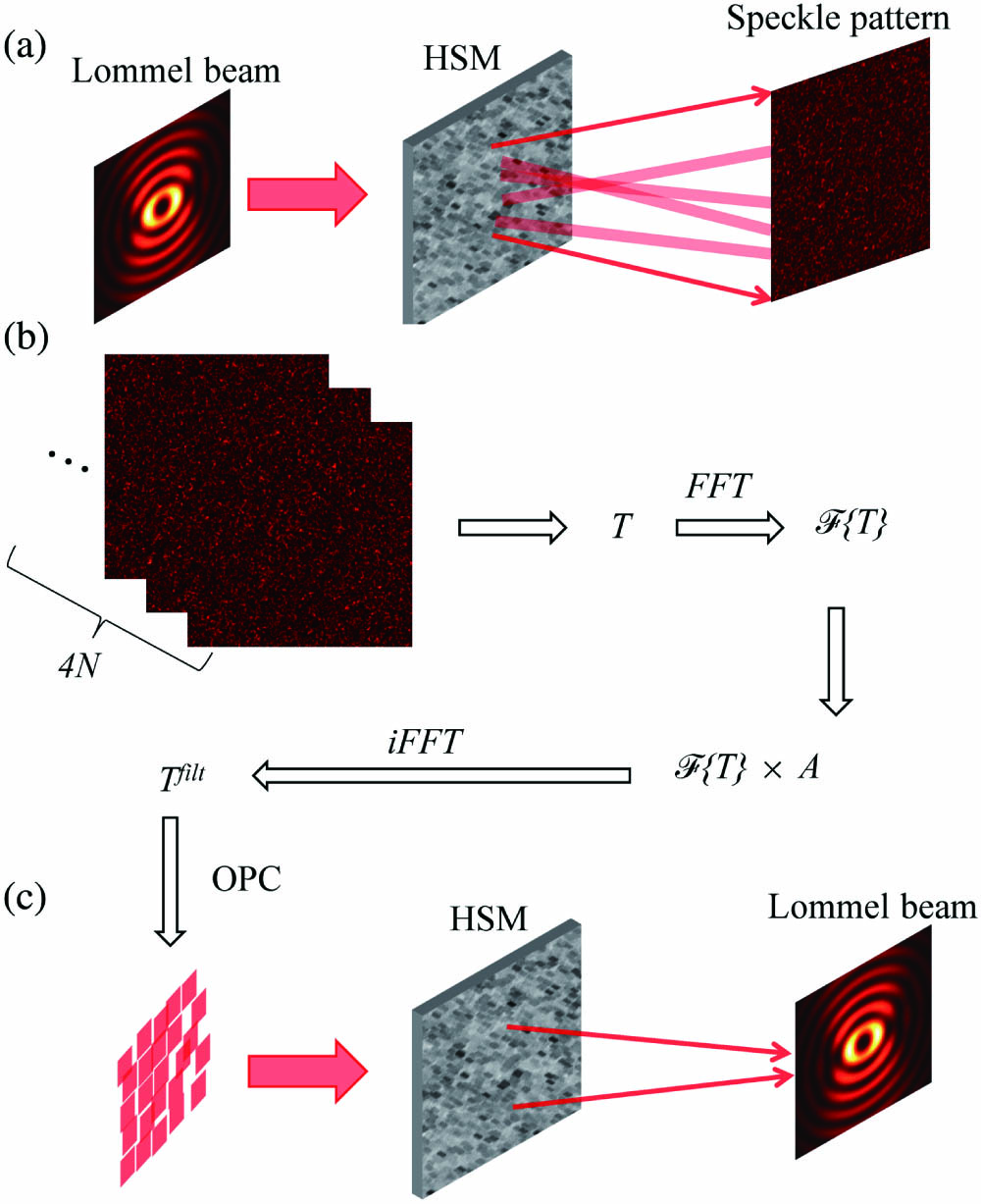
    Fig. 1. Principle of constructing Lommel beams through highly scattering media with TM-based PSF engineering method. (a) When a Lommel beam is incident on a highly scattering medium (HSM), the transmitted light becomes a speckle field due to multiple scattering. (b) Flow chart of TM-based PSF engineering method. (c) With the calculated wavefront as the input field impinging on this HSM, the desired Lommel beam can be obtained at the output plane behind the HSM. OPC, optical phase conjugation.
    Experimental setup. L, lens; M, mirror; BS, beam splitter; DMD, digital micro-mirror device; F, filter; OBJ, objective lens; HSM, ZnO scattering layer; CMOS, complementary metal-oxide-semiconductor camera.
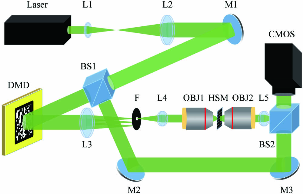
    Fig. 2. Experimental setup. L, lens; M, mirror; BS, beam splitter; DMD, digital micro-mirror device; F, filter; OBJ, objective lens; HSM, ZnO scattering layer; CMOS, complementary metal-oxide-semiconductor camera.
    Creation of Lommel beam with parameters n = 2, c = 0.7, ρ1 = 240, and ρ2 = 40 pixels of the CMOS camera through a highly scattering medium. (a), (b) The theoretical intensity and phase profiles of the Lommel beam. (c), (d) The intensity and phase profiles of the Lommel beam’s angular spectrum. (e), (f) The simulated intensity and phase profiles of the Lommel beam through a highly scattering medium. (g), (h) The measured intensity and phase profiles of the Lommel beam through ZnO scattering layer in experiment. (i), (j) The intensity profiles in (a), (e), and (g) along the white dashed line (x axis) and the blue dashed line (y axis) in (a), respectively.
    Fig. 3. Creation of Lommel beam with parameters n = 2, c = 0.7, ρ1 = 240, and ρ2 = 40 pixels of the CMOS camera through a highly scattering medium. (a), (b) The theoretical intensity and phase profiles of the Lommel beam. (c), (d) The intensity and phase profiles of the Lommel beam’s angular spectrum. (e), (f) The simulated intensity and phase profiles of the Lommel beam through a highly scattering medium. (g), (h) The measured intensity and phase profiles of the Lommel beam through ZnO scattering layer in experiment. (i), (j) The intensity profiles in (a), (e), and (g) along the white dashed line (x axis) and the blue dashed line (y axis) in (a), respectively.
    Construct Lommel beams through a ZnO scattering layer with different parameters c and n. (a)–(d) The intensity profiles of Lommel beams with n = 2 and different c: (a) 0.1, (b) 0.4, (c) 0.7, (d) 0.9. (e)–(h) The phase profiles corresponding to (a)–(d). (i)–(l) The intensity profiles of Lommel beams with c = 0.7 and different topological charges n = 1, 2, 3, 4, respectively. (m)–(p) The phase profiles corresponding to (i)–(l).
    Fig. 4. Construct Lommel beams through a ZnO scattering layer with different parameters c and n. (a)–(d) The intensity profiles of Lommel beams with n = 2 and different c: (a) 0.1, (b) 0.4, (c) 0.7, (d) 0.9. (e)–(h) The phase profiles corresponding to (a)–(d). (i)–(l) The intensity profiles of Lommel beams with c = 0.7 and different topological charges n = 1, 2, 3, 4, respectively. (m)–(p) The phase profiles corresponding to (i)–(l).
    Lommel beams with different orientations were constructed through a ZnO scattering layer experimentally. (a)–(d) The intensity patterns of Lommel beams with different parameters φ0: (a) 0, (b) π/4, (c) π/2, (d) 3π/4, and the same c0 = 0.6, n = 2. (e)–(h) The phase profiles corresponding to (a)–(d), respectively.
    Fig. 5. Lommel beams with different orientations were constructed through a ZnO scattering layer experimentally. (a)–(d) The intensity patterns of Lommel beams with different parameters φ0: (a) 0, (b) π/4, (c) π/2, (d) 3π/4, and the same c0 = 0.6, n = 2. (e)–(h) The phase profiles corresponding to (a)–(d), respectively.
    Raster scanning of Lommel beams and generation of multiple Lommel beams simultaneously through the ZnO scattering layer. The parameters are c0 = 0.7, n = 1, and φ0 = 0. (a)–(f) The raster scanning of Lommel beam. (g)–(i) Construct multiple Lommel beams simultaneously.
    Fig. 6. Raster scanning of Lommel beams and generation of multiple Lommel beams simultaneously through the ZnO scattering layer. The parameters are c0 = 0.7, n = 1, and φ0 = 0. (a)–(f) The raster scanning of Lommel beam. (g)–(i) Construct multiple Lommel beams simultaneously.
    Shijie Tu, Qiannan Lei, Yangjian Cai, Qian Zhao. Generation of Lommel beams through highly scattering media[J]. Chinese Optics Letters, 2022, 20(9): 092501
    Download Citation