• Chinese Journal of Lasers
  • Vol. 51, Issue 1, 0102003 (2024)
Xiaojing Sun, Ding Yuan, Chao Wei, Xiao Yang, and Lin Li*
Author Affiliations
  • Research Center for Laser Extreme Manufacturing, Ningbo Institute of Materials Technology & Engineering, Chinese Academy of Sciences, Ningbo 315201, Zhejiang , China
  • show less
    DOI: 10.3788/CJL231414 Cite this Article Set citation alerts
    Xiaojing Sun, Ding Yuan, Chao Wei, Xiao Yang, Lin Li. Advances in the Study of Interfaces in Laser Additive Manufacturing of Multi‐Materials with Significant Differences in Physical Properties (Invited)[J]. Chinese Journal of Lasers, 2024, 51(1): 0102003 Copy Citation Text show less
    Schematic diagrams of multi-material powder dropping/spreading methods[5,7,12] and material parts with significant differences in physical properties fabricated by L-PBF[5,13]. (a) Blade-based dual powder spreading; (b) ultrasonic-based dual powder dropping; (c) electrophotographic-based dual powder dropping; (d) “blade + ultrasonic” hybrid powder spreading; (e) polymer PA11-Cu10Sn heterostructure; (f) steel-ceramic heterostructure
    Fig. 1. Schematic diagrams of multi-material powder dropping/spreading methods[5,7,12] and material parts with significant differences in physical properties fabricated by L-PBF[5,13]. (a) Blade-based dual powder spreading; (b) ultrasonic-based dual powder dropping; (c) electrophotographic-based dual powder dropping; (d) “blade + ultrasonic” hybrid powder spreading; (e) polymer PA11-Cu10Sn heterostructure; (f) steel-ceramic heterostructure
    Schematic diagram of a material formation system with laser powder-directed energy deposition
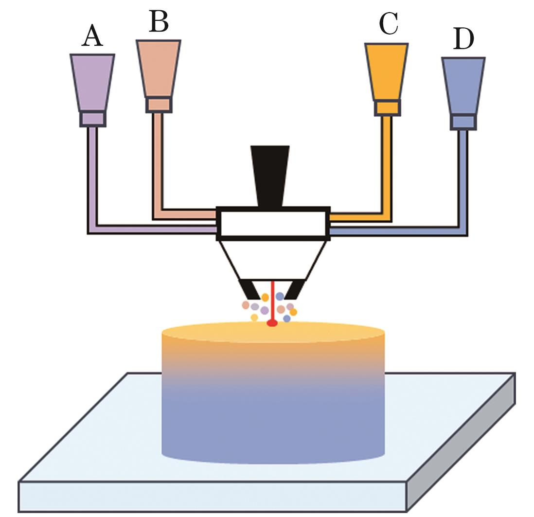
    Fig. 2. Schematic diagram of a material formation system with laser powder-directed energy deposition
    Schematic diagram of laser induced forward transfer (LIFT) and the formed materials with significant differences in physical properties. (a) Schematic diagram of LIFT[20]; (b) graphene-nickel electrode structures[25]; (c) microstructure of Cu-MCMB-GPE-LiCoO2-Al[26]
    Fig. 3. Schematic diagram of laser induced forward transfer (LIFT) and the formed materials with significant differences in physical properties. (a) Schematic diagram of LIFT[20]; (b) graphene-nickel electrode structures[25]; (c) microstructure of Cu-MCMB-GPE-LiCoO2-Al[26]
    Schematic diagram of multiphoton fabrication process and formed metal-polymer material[27]. (a) Schematic diagram of multiphoton fabrication process; (b) polyimide resin substrate trenches; (c) silver-polyimide resin circuit components with significant differences in physical properties
    Fig. 4. Schematic diagram of multiphoton fabrication process and formed metal-polymer material[27]. (a) Schematic diagram of multiphoton fabrication process; (b) polyimide resin substrate trenches; (c) silver-polyimide resin circuit components with significant differences in physical properties
    Schematic diagram of hybrid multi-material laser additive manufacturing (HMM-LAM) and the fabricated multiple materials with significant differences in physical properties[37]. (a) HMM-LAM system integrating fused filament fabrication (FFF) and L-PBF; (b)‒(c) metal-polymer components
    Fig. 5. Schematic diagram of hybrid multi-material laser additive manufacturing (HMM-LAM) and the fabricated multiple materials with significant differences in physical properties[37]. (a) HMM-LAM system integrating fused filament fabrication (FFF) and L-PBF; (b)‒(c) metal-polymer components
    Interface cracking and defect issues of the materials with significant differences in physical properties. (a) 316L stainless steel-polymer PET heterostructure[37]; (b) Invar 36-V component gradient heterostructure[40]; (c) NiCr-YSZ heterostructure interface[41]; (d) Al-316L stainless steel heterostructure interface[42]; (e) Ti6Al4V-Al12Si component gradient heterostructure[17]
    Fig. 6. Interface cracking and defect issues of the materials with significant differences in physical properties. (a) 316L stainless steel-polymer PET heterostructure[37]; (b) Invar 36-V component gradient heterostructure[40]; (c) NiCr-YSZ heterostructure interface[41]; (d) Al-316L stainless steel heterostructure interface[42]; (e) Ti6Al4V-Al12Si component gradient heterostructure[17]
    Laser absorption rate of various materials. (a) Laser absorption rates of common materials at different wavelengths[43]; (b) laser absorption rate of PC and Cu at different wavelengths[44]
    Fig. 7. Laser absorption rate of various materials. (a) Laser absorption rates of common materials at different wavelengths[43]; (b) laser absorption rate of PC and Cu at different wavelengths[44]
    Residual stress and strain due to local molten pool contraction
    Fig. 8. Residual stress and strain due to local molten pool contraction
    Binary phase diagrams of different compounds. (a) Al-Ti[66]; (b) Al-Fe[67]
    Fig. 9. Binary phase diagrams of different compounds. (a) Al-Ti[66]; (b) Al-Fe[67]
    Process optimization. (a) Process optimization of 316L SS-CuSn10 heterostructure interface[86]; (b) process optimization of Ti-Al materials with significant differences in physical properties fabricated by L-PBF, formation parameters optimization of AlSi10Mg[89]
    Fig. 11. Process optimization. (a) Process optimization of 316L SS-CuSn10 heterostructure interface[86]; (b) process optimization of Ti-Al materials with significant differences in physical properties fabricated by L-PBF, formation parameters optimization of AlSi10Mg[89]
    1.2367 tool steel- ZrO2 and Al2O3 ceramic materials with significant differences in physical properties[95]. (a) Interface microstructure before laser re-melting; (b) interface microstructure after laser re-melting
    Fig. 12. 1.2367 tool steel- ZrO2 and Al2O3 ceramic materials with significant differences in physical properties[95]. (a) Interface microstructure before laser re-melting; (b) interface microstructure after laser re-melting
    Interface optimization methods for materials with significant differences in physical properties
    Fig. 12. Interface optimization methods for materials with significant differences in physical properties
    Common functional graded design methods for heterogeneous materials
    Fig. 13. Common functional graded design methods for heterogeneous materials
    Transition bonding. (a)‒(h) Macroscopic and microscopic morphology of direct bonding, mixture bonding, and transition bonding of Cu10Sn-W heterostructure formed by L-PBF[96]; (i)‒(l) microscopic morphology and deformation under compression load of Ti-Al gyroscope heterostructure with significant differences in physical properties formed by L-PBF[97]
    Fig. 14. Transition bonding. (a)‒(h) Macroscopic and microscopic morphology of direct bonding, mixture bonding, and transition bonding of Cu10Sn-W heterostructure formed by L-PBF[96]; (i)‒(l) microscopic morphology and deformation under compression load of Ti-Al gyroscope heterostructure with significant differences in physical properties formed by L-PBF[97]
    LAMed gradient materials with significant differences in physical properties. (a) Heterostructure of Fe-Al discontinuous gradient materials[98]; (b)(c) DED formed Fe-Al discontinuous gradient samples and the microstructures of various regions of the samples[98]; (d) Ti-Al continuous gradient materials[16]; (e)‒(g) microstructures of Ti-Al continuous gradient materials formed by L-PBF[16]
    Fig. 15. LAMed gradient materials with significant differences in physical properties. (a) Heterostructure of Fe-Al discontinuous gradient materials[98]; (b)(c) DED formed Fe-Al discontinuous gradient samples and the microstructures of various regions of the samples[98]; (d) Ti-Al continuous gradient materials[16]; (e)‒(g) microstructures of Ti-Al continuous gradient materials formed by L-PBF[16]
    Al-Ti heterostructure with significant differences in physical properties fabricated by the composite system of LAM+cold spraying[38]. (a)(c) Al-Ti6Al4V heterostructure with significant differences in physical properties and its interface morphology; (b)(d) Al+Al2O3 mixture-Ti6Al4V heterostructure with significant differences in physical properties and its interface morphology
    Fig. 16. Al-Ti heterostructure with significant differences in physical properties fabricated by the composite system of LAM+cold spraying[38]. (a)(c) Al-Ti6Al4V heterostructure with significant differences in physical properties and its interface morphology; (b)(d) Al+Al2O3 mixture-Ti6Al4V heterostructure with significant differences in physical properties and its interface morphology
    Simulation results of L-PBF materials with significant differences in physical properties. (a) Thermal boundary conditions of the calculation domain of 316L stainless steel-Cu10Sn heterointerface and simulation results of temperature field distribution at laser melting heterointerface and track morphology after solidification[87]; (b) simulation results of track morphology after solidification, component distribution and molten pool morphology of laser melted mixed IN718-Cu10Sn powder beds under different hatch spacings[90]; (c) finite element model of Ti6Al4V-TiB2 heterostructure and temperature distribution of the cross-section molten pool of laser melted TiB2 layer at different laser powers[91]
    Fig. 17. Simulation results of L-PBF materials with significant differences in physical properties. (a) Thermal boundary conditions of the calculation domain of 316L stainless steel-Cu10Sn heterointerface and simulation results of temperature field distribution at laser melting heterointerface and track morphology after solidification[87]; (b) simulation results of track morphology after solidification, component distribution and molten pool morphology of laser melted mixed IN718-Cu10Sn powder beds under different hatch spacings[90]; (c) finite element model of Ti6Al4V-TiB2 heterostructure and temperature distribution of the cross-section molten pool of laser melted TiB2 layer at different laser powers[91]
    Forming processAdvantageLimitation
    Laser powder bed fusion(L-PBF)

    Forming precision

    Diversity of material selection

    Process efficiency

    Powder recycling and reuse

    Laser-directed energy deposition(L-DED)

    Multi-material powder feeding

    Large size formed parts

    Support structures

    Surface roughness

    Laser induced forward transfer(LIFT)Microscale formingProcess efficiency for 3D
    Multiphoton fabrication(MF)High resolution and precisionLimitation in materials
    Hybrid multi-material laser additive manufacturing(HMM-LAM)Flexibility of structureComplex to control
    Table 1. Advantages and limitations of multi-material laser additive manufacturing technologies
    MetalMelting point /℃Thermal conductivity /(W·m-1·K-1CTE(αRef.
    Temperature /℃α value /(10-6-1
    Pure aluminum6602052023.254
    Pure copper10853982016.6‒17.554-55
    Pure iron1535802012.254
    316 stainless steel(316 SS)1392‒144416‒2420‒10016.056
    Pure nickel1455912013.054
    Invar 36142710‒1120‒1001.356
    Pure titanium166822208.6‒10.857
    Table 2. Thermophysical properties of typical metals in additive manufacturing
    Interface optimization methodDissimilar materialMM-LAM processRef.
    Process optimizationParameters optimization316L SS-Cu10SnL-PBF86-87
    316L SS-CuCrZrL-PBF88
    Ti6Al4V-AlSi10MgL-PBF89
    IN718-Cu10SnL-PBF90
    Ti6Al4V-TiB2L-PBF91-92
    Heat treatment processW-316L SSL-PBF93
    Laser re-meltingTi6Al4V-Cu10SnL-PBF94
    1.2367 steel-ceramic ZrO2+Al2O3L-PBF95
    Functional gradient designTransition bondingCu10Sn-WL-PBF96
    Ti6Al4V-AlCuMgL-PBF97
    Gradient bondingFe-Al12SiL-PBF98
    Ti6Al4V-AlSi10MgL-DED16
    Interface structure design316L SS-polymer PETL-PBF37
    316L SS-CuSn10L-PBF99-100
    Integrated manufacturing systemLaser wavelength selectionCu-AISI 304L SSL-DED45
    Multi-energy fields hybridTi6Al4V- AlHMM-LAM38
    Ti6Al4V-Al+Al2O3HMM-LAM38
    316L SS-polymer PLAHMM-LAM37
    Table 3. Interface optimization methods and related literatures for materials with significant differences in physical properties
    Wavelength /nmSpectral absorptance for material /%
    CopperAluminiumStainless steelTitanium
    457(blue laser)65.213.643.280.8
    525(green laser)54.513.540.278.6
    1085(infrared laser)4.05.230.165.2
    Table 4. Spectral absorptance for copper, aluminium, stainless steel and titanium at blue, green and infrared laser wavelengths[101]
    Xiaojing Sun, Ding Yuan, Chao Wei, Xiao Yang, Lin Li. Advances in the Study of Interfaces in Laser Additive Manufacturing of Multi‐Materials with Significant Differences in Physical Properties (Invited)[J]. Chinese Journal of Lasers, 2024, 51(1): 0102003
    Download Citation