• High Power Laser Science and Engineering
  • Vol. 7, Issue 2, 02000e24 (2019)
C. D. Armstrong1、2、†,*, C. M. Brenner2, C. Jones3, D. R. Rusby2, Z. E. Davidson1, Y. Zhang2、4, J. Wragg2, S. Richards2, C. Spindloe2, P. Oliveira2, M. Notley2, R. Clarke2, S. R. Mirfayzi5, S. Kar5, Y. Li4, T. Scott3, P. McKenna1, and D. Neely2
Author Affiliations
  • 1Department of Physics SUPA, University of Strathclyde, Glasgow G4 0NG, UK
  • 2Central Laser Facility, STFC Rutherford Appleton Laboratory, Harwell, Oxford OX11 0QX, UK
  • 3Interface Analysis Centre, HH Wills Physics Laboratory, Tyndall Avenue, Bristol BS8 1TL, UK
  • 4Beijing National Laboratory for Condensed Matter Physics, Institute of Physics, Chinese Academy of Sciences, Beijing 100190, China
  • 5Centre for Plasma Physics, Queen’s University Belfast, Belfast BT7 1NN, UK
  • show less
    DOI: 10.1017/hpl.2019.8 Cite this Article Set citation alerts
    C. D. Armstrong, C. M. Brenner, C. Jones, D. R. Rusby, Z. E. Davidson, Y. Zhang, J. Wragg, S. Richards, C. Spindloe, P. Oliveira, M. Notley, R. Clarke, S. R. Mirfayzi, S. Kar, Y. Li, T. Scott, P. McKenna, D. Neely. Bremsstrahlung emission from high power laser interactions with constrained targets for industrial radiography[J]. High Power Laser Science and Engineering, 2019, 7(2): 02000e24 Copy Citation Text show less

    Abstract

    Laser–solid interactions are highly suited as a potential source of high energy X-rays for nondestructive imaging. A bright, energetic X-ray pulse can be driven from a small source, making it ideal for high resolution X-ray radiography. By limiting the lateral dimensions of the target we are able to confine the region over which X-rays are produced, enabling imaging with enhanced resolution and contrast. Using constrained targets we demonstrate experimentally a $(20\pm 3)~\unicode[STIX]{x03BC}\text{m}$ X-ray source, improving the image quality compared to unconstrained foil targets. Modelling demonstrates that a larger sheath field envelope around the perimeter of the constrained targets increases the proportion of electron current that recirculates through the target, driving a brighter source of X-rays.

    1 Introduction

    High intensity laser pulses rapidly ionize and accelerate electrons in laser–solid interactions, driving a multi-megaampere current of relativistic electrons into the target[13]. This electron current produces a bright source of bremsstrahlung radiation as it propagates, which has long been used as a source for radiography[411] and as a diagnostic for the internal electron current[1215]. In contrast to conventional sources of X-ray radiation, laser-driven sources are able to deliver a broad (keV to tens of MeV) range of energies in a duration on the order of the laser pulse (${\sim}$ps) from a small (${<}100~\unicode[STIX]{x03BC}\text{m}$) source[6, 16]. High energy laser pulses (${>}100$ J) offer the potential of single-shot acquisition through larger industrial samples when combined with thick (${>}10~\unicode[STIX]{x03BC}\text{m}$) high-Z targets due to the high flux of energetic X-rays produced during the interaction. With the advent of high repetition rate high power lasers, commercial interest in using laser-driven sources has grown[17, 18].

    A key advantage of laser-driven systems, compared to conventional X-ray sources, is the flexibility offered. By altering laser and target conditions the X-ray beam properties can be varied to suit the sample. Prior work has demonstrated that the spectral emission can be altered by varying laser and target conditions[14, 19, 20]. Modifying the target shape provides a simple mechanism to optimize the flux and spatial source size for industrial radiography. X-ray sources ${<}150~\unicode[STIX]{x03BC}\text{m}$ in size for thick high-Z targets[7] have been successfully demonstrated during previous experimental campaigns. Using laser-driven X-ray sources as a backlighter in inertial confinement fusion has also been an area of study, where experimental investigations have demonstrated a bright $\text{K}\unicode[STIX]{x03B1}$ emission with the side profile of the target as the source[16, 2123]. While this technique has achieved a source size of $(5.5\pm 1.0)~\unicode[STIX]{x03BC}\text{m}$, the flux of X-rays emitted from the target edge is lower than on laser axis and target normal[24, 25]. Bremsstrahlung sources of $(30\pm 10)~\unicode[STIX]{x03BC}\text{m}$ have been demonstrated during laser-wakefield experiments using a bremsstrahlung converter positioned after the laser–gas interaction[26]. With wakefield generation, electrons are significantly higher in energy than those generated in laser–solid interactions and therefore scatter less through converter targets, producing smaller source sizes with narrow divergence[27]. However, laser–solid interactions convert a significantly higher proportion of laser energy to hot electrons[27, 28] with a larger emitted beam divergence, which is advantageous to industrial scale imaging requirements. In this paper, we report on results from a recent experimental campaign using constrained targets to reduce the X-ray emission area and drive a bright X-ray source through increased refluxing of hot electrons and increase the flux by ${\sim}50\%$ compared to unconstrained foil targets of comparable thickness.

    2 Experimental campaign

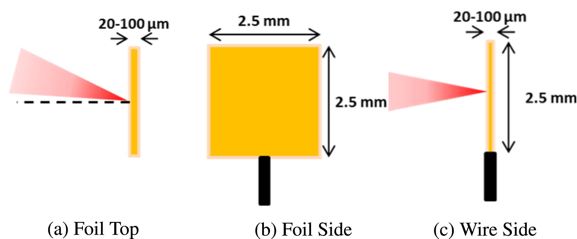
    The experiment was conducted using the Vulcan laser system[29]. The target variations are displayed in Figure 1. Laser energy was 250 J and the pulse duration was ${\sim}14$ ps providing a peak intensity of ${\sim}1\times 10^{19}~\text{W}/\text{cm}^{2}$. The incident angle for foil targets was fixed at $5^{\circ }$ relative to the target normal. The experimental layout, shown in Figure 2, provided sufficient magnification for the main imaging line. Primary diagnostics for the spatial and spectral measurements are discussed in their respective sections. A high strength (0.6 T) magnet was positioned behind the target rear surface to ensure that charged particle emission did not contribute to the measured X-ray signal.

    3 Spatial emission

    The X-ray source size was measured via a set of on-axis penumbral foils. The penumbral foil set has $300~\unicode[STIX]{x03BC}\text{m}$ tungsten slabs curved to a radius of ($152\pm 2$) mm to ensure that the transmission length of the X-rays sufficiently attenuates up to 100 keV energies at a small depth (${<}1~\unicode[STIX]{x03BC}\text{m}$) into the foil. This curvature also ensures that part of the foil is perpendicular to the incoming beam. One foil was positioned to measure the vertical source (V-Foil) and one for the horizontal (H-Foil). The setup, shown in Figure 2, provided a magnification of $\times 17.5$ for the horizontal axis and $\times 13.4$ for the vertical axis. The X-rays were detected using layers of Fujifilm SR image plate (IP). Filtering from the 2 mm Al chamber port when combined with the IP sensitivity provided peak absorption at ${\sim}35$ keV. Uncertainty in measurements with the penumbral foil is a convolution of both the point-spread function (PSF) – dominated by X-rays scattering through filter materials – and minimum resolution bounds shown by Fiksel et al. to be $(118\pm 2)~\unicode[STIX]{x03BC}\text{m}$[30].

    The observed X-ray signal is a convolution of two sources; the first, a bright central source generated as the main electron channel propagates through the target, and the second, a diffuse source dominated by electrons recirculating through the target substrate after their first pass, see penumbral schematic in Figure 3. The large field of view provided by the penumbral foil allows measurement of both components of the X-ray source. The penumbral radiographs demonstrate the effect of switching from foil to wire targets, shown in Figure 4. The substrate feature from the foil introduces a large (${\sim}1$ mm) blurring function into radiographs contributing similar levels of flux to the central source. When switching to a wire this substrate source is removed and all flux is contributed by the single source. The source is asymmetric for wire targets as the electrons are only restricted in the horizontal axis. Using the edge of a foil, or supported wire targets, has previously demonstrated 1D and 2D restriction of the X-ray source[11, 16]. Figure 5(a) shows the horizontal axis measurement decreasing with decreasing target thickness, but when measuring the vertical source size we see a relatively constant response – the X-ray source measuring ${\sim}60~\unicode[STIX]{x03BC}\text{m}$ irrespective of wire diameter. In radiographs this presents as an asymmetric blurring function giving poorer resolution in the vertical axis than in the horizontal. This effect is not present for foil targets as we see the horizontal and vertical sources are quasi-symmetric and instead both axes have the same blurring function.

    4 Spectral emission

    Using the imaging detectors and two off-axis scintillator-based hard X-ray spectrometers[31], we measured the on-shot flux and spectra for each target configuration. As demonstrated in Figure 5, the effective X-ray temperature for the wire and foil targets is similar, yet the flux contributed by wire targets is ${\sim}50\%$ higher than by foils of a similar thickness. Increasing flux and effective temperature with target thickness is expected. Larger targets attenuate more of the soft X-ray emission and artificially harden the emitted spectrum, and increase the likelihood of electrons interacting with the background material – emitting bremsstrahlung – on their first pass through the target. To explain the increase when the target geometry changes we consider the effect that the sheath is having on the internal electron population. An electrostatic field builds on the target surfaces proportional to the number density of electrons that reach the surface. As such, for the same number of electrons the relative strength is governed by the surface area over which electrons are spread. In foil targets, the total available surface area is $A_{\text{foil}}=2(lh+lw+hw)$, where $l$, $w$ and $h$ are the target thickness, width and height, respectively; for a wire this becomes $A_{\text{wire}}=2\unicode[STIX]{x1D70B}r(r+h)$, where $r$ is the radius of the wire. In the case where $2r=l$ and $h>r$, it can be shown that for a foil target with $w>l(\unicode[STIX]{x1D70B}-2)/2$ the surface area is larger than that of a wire. As such, the number density of electrons at the surface, and field strength, will generally be lower for a foil than for a wire. Electrons accelerated later in time are therefore more likely to recirculate in the wire, as the average field strength will be higher.

    5 PIC modelling

    From particle-in-cell (PIC) simulations we are able to probe the varying flux more directly. The simulations were conducted with EPOCH[32] in 2D, focusing a $5\times 10^{19}~\text{W}/\text{cm}^{2}$ laser onto the surface of a $25~\unicode[STIX]{x03BC}\text{m}$ target. The pulse duration was 250 fs and the simulation was conducted for 850 fs, and the results shown in Figures 6(a) and 6(b) were taken at 500 fs where both the wire and foil targets had their peak sheath field. The simulations compared the effect of a standing wire and a foil to probe the difference in internal electron density, and therefore resultant X-ray emission. Variation in the scale length has been shown to have a significant effect on the electron dynamics and resultant X-ray yield[33, 34]; as such, in order to focus on the effect of the geometry, both simulations included a $2~\unicode[STIX]{x03BC}\text{m}$ plasma scale length on the front surface[35, 36].

    The simulation results are shown in Figure 6. We see a large increase in electron density within the wire target compared to the standard foil over the duration of the simulation. The predicted increase in field strength established on the wire compared to that of the foil in the simulation is shown in Figures 6(a) and 6(b). This change in field strength drives the internal electron density higher for the wire targets, shown in Figure 6(c). The electrons are limited to $E>2.5$ MeV in the density and spectra plots as electrons below this energy are dominated by collisional stopping rather than radiation[37]. Absorption through the simulations was equal for both target geometries. For the wire, as there is a higher potential field surrounding more of the target surface, more electrons are constrained within the target. As the electrons recirculate through the target their energy changes and as a result the total spectra over the lifetime of the simulation vary for each geometry.

    ParameterWireFoil
    $T_{\text{hot}/\text{MeV}}$1.92.1
    $T_{\text{cold}/\text{MeV}}$1.31.2
    $N_{\text{electron}/10^{18}}$5.73.7
    $N_{\unicode[STIX]{x1D6FE}}$2.41
    $\unicode[STIX]{x1D702}_{e\rightarrow \unicode[STIX]{x1D6FE}/\%}$9.662.7

    Table 1. EPOCH and GEANT4 simulation results, $N_{\unicode[STIX]{x1D6FE}}$ for the wire simulations is normalized to the foil results.

    In wire targets, where there is less surface area for electrons to escape from, we see significantly more low energy electrons remaining within the target, whereas, in the foil, these same electrons would be able to escape laterally where the sheath field is weaker. This results in a cooler two-temperature distribution for the wire target (Figure 6(d) and Table 1). As EPOCH cannot intrinsically determine the X-ray radiation, the internal electron spectra were used in a Monte–Carlo simulation with GEANT4[38, 39] to determine the expected X-ray flux – simulated as a Maxwell–Juttner distribution from 10 keV to 25 MeV to account for the lower energy electrons not included in the EPOCH output. It is necessary to have the full spectra over the PIC simulation to account for the variation in energy of refluxing electrons that GEANT4 cannot simulate[9]. In order to approximate the increase in path length for the refluxing electrons, an electric field was applied to the target surfaces. The strength of the field was set to 4 TV/m. $10^{6}$ electrons passed through a gold foil 25–$500~\unicode[STIX]{x03BC}\text{m}$ thick and a gold wire $25~\unicode[STIX]{x03BC}\text{m}$ thick.

    The simulation results, in Figure 7 and Table 1, demonstrate the increase in overall flux for a wire target compared to an equally thick foil target. The increase in X-ray flux from the GEANT4 simulations is the result of the change in the two-temperature electron distribution. The more populous high energy tail of the wire target, shown in Figure 6(d), generates bremsstrahlung more readily as it travels through the target resulting in the increase seen in Figure 7(a). The effective temperature of the simulated emitted spectra increases more than that of the measured results (Figure 7(b)), indicating that the recirculating population has changed for the thicker foil targets. These results likely underestimate the low energy X-ray flux as the EPOCH output does not include energies below 2.5 MeV – the significant increase in $N_{\text{electron}}$ for the wire target, however, suggest that the underestimation would favour the wire geometry. The spatial distribution from the GEANT4 simulations is shown in Figures 8(a) and 8(b) for the foil and wire, respectively; for the wire we see a clear asymmetry in the source with electrons being directed up and down the wire.

    6 Radiographs

    Imaging and source measurements were taken independently so as not to interfere with the image. The industrial sample is a scaled nuclear waste container. It consists of a 5 cm diameter steel canister containing a uranium penny sample encased in grout. The sample has previously been characterized in an X-ray transmission (XRT) machine (Figure 9(a)). The uranium underwent controlled corrosion after being encased in grout resulting in expansion of the penny and cracks forming within the grout[40]. Figures 9(a)–9(c) demonstrate that these cracks, which are indicators of containment failure, are resolved in both the heavily processed XRT image and the two single exposure laser-driven X-ray images: a key proof of concept for radiographic inspection. Using the reduced source size and removal of the substrate source demonstrated with wire targets, a $100~\unicode[STIX]{x03BC}\text{m}$ Au wire target was used to ensure high resolution imaging and sufficient flux to maximize the image contrast. The difference in the edge-spread function (ESF) is displayed in Figure 9(d). The full width at half-maximum (FWHM) of the ESF for the foil is ${\sim}2$ mm and for the wire is ${\sim}0.8$ mm at $5\times$ magnification demonstrating a significant improvement in the quality of the image.

    7 Conclusions

    Using constrained targets produces a significantly smaller, higher contrast, and higher flux X-ray source compared to standard foil targets. The results were measured via a penumbral foil and practically demonstrated with a $\times 2.6$ improvement in image quality with a radiograph of a nuclear test sample. The increase in spatial contrast is due to the limited area over which X-rays can be produced, there is no lateral spreading in the source. The flux is improved relative to similar targets due to the increased electron recirculation within wire targets. The electrostatic potential builds around the full extent of the wire limiting the pathways that electrons can escape from the target, driving a larger and cooler electron spectrum. This provides a simple targetry change that drives a higher flux, higher spatial resolution image without compromising the spectral emission for X-ray radiography. The orientation of the wire confined the X-ray emission in one axis; however, by aligning the target horizontally and optimizing the wire length to electron temperature we expect to retain similar contrast improvements in both axis.

    References

    [1] A. R. Bell, J. R. Davies, S. Guerin, H. Ruhl. Plasma Phys. Control. Fusion, 39, 653(1997).

    [2] F. N. Beg, A. R. Bell, A. E. Dangor, C. N. Danson, A. P. Fews, M. E. Glinsky, B. A. Hammel, P. Lee, P. A. Norreys, M. Tatarakis. Phys. Plasmas, 4, 447(1997).

    [3] P. Gibbon. Short Pulse Laser Interactions with Matter(2004).

    [4] M. D. Perry, J. A. Sefcik, T. Cowan, S. Hatchett, A. Hunt, M. Moran, D. Pennington, R. Snavely, S. C. Wilks. Rev. Sci. Instrum., 70, 265(1999).

    [5] R. D. Edwards, M. A. Sinclair, T. J. Goldsack, K. Krushelnick, F. N. Beg, E. L. Clark, A. E. Dangor, Z. Najmudin, M. Tatarakis, B. Walton, M. Zepf, K. W. D. Ledingham, I. Spencer, P. A. Norreys, R. J. Clarke, R. Kodama, Y. Toyama, M. Tampo. Appl. Phys. Lett., 80, 2129(2002).

    [6] H. S. Park, N. Izuml, M. H. Key, J. A. Koch, O. L. Landen, P. K. Patel, T. W. Phillips, B. B. Zhang. Rev. Sci. Instrum., 75, 404850(2004).

    [7] C. M. Brenner, S. R. Mirfayzi, D. R. Rusby, C. Armstrong, A. Alejo, L. A. Wilson, R. Clarke, H. Ahmed, N. M. H. Butler, D. Haddock, A. Higginson, A. McClymont, C. Murphy, M. Notley, P. Oliver, R. Allott, C. Hernandez-Gomez, S. Kar, P. McKenna, D. Neely. Plasma Phys. Control. Fusion, 58, 014039(2015).

    [8] P. A. Norreys, M. Santala, E. Clark, M. Zepf, I. Watts, F. N. Beg, K. Krushelnick, M. Tatarakis, A. E. Dangor, X. Fang, P. Graham, T. McCanny, R. P. Singhal, K. W. D. Ledingham, A. Creswell, D. C. W. Sanderson, J. Magill, A. Machacek, J. S. Wark, R. Allott, B. Kennedy, D. Neely. Phys. Plasmas, 6, 2150(1999).

    [9] F. Fiorini, D. Neely, R. J. Clarke, S. Green. Laser Part. Beams, 32, 233(2014).

    [10] K. Vaughan, A. S. Moore, V. Smalyuk, K. Wallace, D. Gate, S. G. Glendinning, S. McAplin, H. S. Park, C. Sorce, R. M. Stevenson. High Energy Density Phys., 9, 635(2013).

    [11] E. Brambrink, S. Baton, M. Koenig, R. Yurchak, N. Bidaut, B. Albertazzi, J. E. Cross, G. Gregori, A. Rigby, E. Falize, A. Pelka, F. Kroll, S. Pikuz, Y. Sakawa, N. Ozaki, C. Kuranz, M. Manuel, C. Li, P. Tzeferacos, D. Lamb. High Power Laser Sci. Eng., 4, e30(2016).

    [12] D. M. O’Neill, C. L. S. Lewis, D. Neely, S. J. Davidson, S. J. Rose, R. W. Lee. Phys. Rev. A, 44, 2641(1991).

    [13] C. D. Chen, J. A. King, M. H. Key, K. U. Akli, F. N. Beg, H. Chen, R. R. Freeman, A. Link, A. J. MacKinnon, A. G. MacPhee, P. K. Patel, M. Porkolab, R. B. Stephens, L. D. Van Woerkom. Rev. Sci. Instrum., 79, 130(2008).

    [14] A. L. Meadowcroft, R. D. Edwards. IEEE Trans. Plasma Sci., 40, 1992(2012).

    [15] D. Rusby, R. Gray, N. Butler, R. Dance, G. Scott, V. Bagnoud, B. Zielbauer, P. McKenna, D. Neely. EPJ Web Conf., 167, 02001(2018).

    [16] H. S. Park, B. R. Maddox, E. Giraldez, S. P. Hatchett, L. T. Hudson, N. Izumi, M. H. Key, S. Le Pape, A. J. MacKinnon, A. G. MacPhee, P. K. Patel, T. W. Phillips, B. A. Remington, J. F. Seely, R. Tommasini, R. Town, J. Workman, E. Brambrink. Phys. Plasmas, 75, 404850(2004).

    [17] C. P. Jones, C. M. Brenner, C. A. Stitt, C. D. Armstrong, D. R. Rusby, S. R. Mirfayzi, L. A. Wilson, H. Ahmed, R. Allott, N. M. H. Butler, R. J. Clarke, D. Haddock, C. Hernandez-Gomez, A. Higginson, C. D. Murphy, C. Paraskevoulakos, P. McKenna, D. Neely, S. Kar, T. B. Scott. J. Hazard. Mater., 318, 694(2015).

    [18] P. Mason, M. Divoky, K. Ertel, J. Pilar, T. Butcher, M. Hanus, S. Banerjee, J. Phillips, J. Smith, M. De Vido, A. Lucianetti, C. Hernandez-Gomez, C. Edwards, T. Mocek, J. Collier. Optica, 4, 438(2017).

    [19] G. H. McCall. J. Phys. D: Appl. Phys., 15, 823(1982).

    [20] J. Galy, M. Maucec, D. J. Hamilton, R. Edwards, J. Magill. New J. Phys., 9, 23(2007).

    [21] E. Brambrink, H. G. Wei, B. Barbrel, P. Audebert, A. Benuzzi-Mounaix, T. Boehly, T. Endo, C. Gregory, T. Kimura, R. Kodama, N. Ozaki, H. S. Park, M. Le Gloahec, M. Rabec, M. Koenig. Phys. Plasmas, 16, 033101(2009).

    [22] R. Tommasini, A. MacPhee, D. Hey, T. Ma, C. Chen, N. Izumi, W. Unites, A. MacKinnon, S. P. Hatchett, B. A. Remington, H. S. Park, P. Springer, J. A. Koch, O. L. Landen, J. Seely, G. Holland, L. Hudson. Rev. Sci. Instrum., 79, 10E901(2008).

    [23] H. S. Park, D. M. Chambers, H. K. Chung, R. J. Clarke, R. Eagleton, E. Giraldez, T. Goldsack, R. Heathcote, N. Izumi, M. H. Key, J. A. King, J. A. Koch, O. L. Landen, A. Nikroo, P. K. Patel, D. F. Price, B. A. Remington, H. F. Robey, R. A. Snavely, D. A. Steinman, R. B. Stephens, C. Stoeckl, M. Storm, M. Tabak, W. Theobald, R. P. J. Town, J. E. Wickersham, B. B. Zhang. Phys. Plasmas, 13, 056309(2006).

    [24] B. Westover, A. MacPhee, C. Chen, D. Hey, T. Ma, B. Maddox, H. S. Park, B. Remington, F. N. Beg. Phys. Plasmas, 17, 082703(2010).

    [25] C. Courtois, R. Edwards, A. Compant La Fontaine, C. Aedy, S. Bazzoli, J. L. Bourgade, J. Gazave, J. M. Lagrange, O. Landoas, L. Le Dain, D. Mastrosimone, N. Pichoff, G. Pien, C. Stoeckl. Phys. Plasmas, 20, 083114(2013).

    [26] A. Ben-Ismail, O. Lundh, C. Rechatin, J. K. Lim, J. Faure, S. Corde, V. Malka. Appl. Phys. Lett., 98, 98(2011).

    [27] F. Albert, A. G. R. Thomas, S. P. D. Mangles, S. Banerjee, S. Corde, A. Flacco, M. Litos, D. Neely, J. Vieira, Z. Najmudin, R. Bingham, C. Joshi, T. Katsouleas. Plasma Phys. Control. Fusion, 56, 084015(2014).

    [28] J. R. Davies. Plasma Phys. Control. Fusion, 51, 014006(2009).

    [29] C. N. Danson, P. A. Brummitt, R. J. Clarke, J. L. Collier, B. Fell, A. J. Frackiewicz, S. Hancock, S. Hawkes, C. Hernandez-Gomez, P. Holligan, M. H. R. Hutchinson, A. Kidd, W. J. Lester, I. O. Musgrave, D. Neely, D. R. Neville, P. A. Norreys, D. A. Pepler, C. J. Reason, W. Shaikh, T. B. Winstone, R. W. W. Wyatt, B. E. Wyborn. Nucl. Fusion, 44, S239(2004).

    [30] G. Fiksel, F. J. Marshall, C. Mileham, C. Stoeckl. Rev. Sci. Instrum., 83, 88(2012).

    [31] D. R. Rusby, C. D. Armstrong, C. M. Brenner, P. McKenna, D. Neely. Rev. Sci. Instrum., 89, 073502(2018).

    [32] T. D. Arber, K. Bennett, C. S. Brady, A. Lawrence-Douglas, M. G. Ramsay, N. J. Sircombe, P. Gillies, R. G. Evans, H. Schmitz, A. R. Bell, C. P. Ridgers. Plasma Phys. Control. Fusion, 57, 113001(2015).

    [33] L. C. Jarrott, A. J. Kemp, L. Divol, D. Mariscal, B. Westover, C. McGuffey, F. N. Beg, M. Suggit, C. Chen, D. Hey, B. Maddox, J. Hawreliak, H. S. Park, B. Remington, M. S. Wei, A. Macphee. Phys. Plasmas, 21, 031211(2014).

    [34] V. M. Ovchinnikov, D. W. Schumacher, M. McMahon, E. A. Chowdhury, C. D. Chen, A. Morace, R. R. Freeman. Phys. Rev. Lett., 110, 065007(2013).

    [35] M. I. Santala, M. Zepf, I. Watts, F. N. Beg, E. Clark, M. Tatarakis, K. Krushelnick, A. E. Dangor, T. McCanny, I. Spencer, R. P. Singhal, K. W. Ledingham, S. C. Wilks, A. C. Machacek, J. S. Wark, R. Allott, R. J. Clarke, P. A. Norreys. Phys. Rev. Lett., 84, 1459(2000).

    [36] P. McKenna, D. C. Carroll, O. Lundh, F. Nurnberg, K. Markey, S. Bandyopadhyay, D. Batani, R. G. Evans, R. Jafer, S. Kar, D. Neely, D. Pepler, M. N. Quinn, R. Redaelli, M. Roth, C. G. Wahlstrm, X. H. Yuan, M. Zepf. Laser Part. Beams, 26, 591(2008).

    [37] M. Berger, J. Coursey, M. Zucker, J. Chang.

    [38] S. Agostinelli, J. Allison, K. Amako, J. Apostolakis, H. Araujo, P. Arce, M. Asai, D. Axen, S. Banerjee, G. Barrand, F. Behner, L. Bellagamba, J. Boudreau, L. Broglia, A. Brunengo, H. Burkhardt, S. Chauvie, J. Chuma, R. Chytracek, G. Cooperman, G. Cosmo, P. Degtyarenko, A. Dell’Acqua, G. Depaola, D. Dietrich, R. Enami, A. Feliciello, C. Ferguson, H. Fesefeldt, G. Folger, F. Foppiano, A. Forti, S. Garelli, S. Giani, R. Giannitrapani, D. Gibin, J. J. Gomez Cadenas, I. Gonzalez, G. Gracia Abril, G. Greeniaus, W. Greiner, V. Grichine, A. Grossheim, S. Guatelli, P. Gumplinger, R. Hamatsu, K. Hashimoto, H. Hasui, A. Heikkinen, A. Howard, V. Ivanchenko, A. Johnson, F. W. Jones, J. Kallenbach, N. Kanaya, M. Kawabata, Y. Kawabata, M. Kawaguti, S. Kelner, P. Kent, A. Kimura, T. Kodama, R. Kokoulin, M. Kossov, H. Kurashige, E. Lamanna, T. Lampen, V. Lara, V. Lefebure, F. Lei, M. Liendl, W. Lockman, F. Longo, S. Magni, M. Maire, E. Medernach, K. Minamimoto, P. Mora de Freitas, Y. Morita, K. Murakami, M. Nagamatu, R. Nartallo, P. Nieminen, T. Nishimura, K. Ohtsubo, M. Okamura, S. O’Neale, Y. Oohata, K. Paech, J. Perl, A. Pfeiffer, M. G. Pia, F. Ranjard, A. Rybin, S. Sadilov, E. di Salvo, G. Santin, T. Sasaki, N. Savvas, Y. Sawada, S. Scherer, S. Sei, V. Sirotenko, D. Smith, N. Starkov, H. Stoecker, J. Sulkimo, M. Takahata, S. Tanaka, E. Tcherniaev, E. Safai Tehrani, M. Tropeano, P. Truscott, H. Uno, L. Urban, P. Urban, M. Verderi, A. Walkden, W. Wander, H. Weber, J. P. Wellisch, T. Wenaus, D. C. Williams, D. Wright, T. Yamada, H. Yoshida, D. Zschiesche. Nucl. Instrum. Methods Phys. Res. A, 506, 250(2003).

    [39] E. Acosta, X. Llovet, F. Salvat. Appl. Phys. Lett., 80, 3228(2002).

    [40] C. P. Jones, C. M. Brenner, C. D. Armstrong, D. R. Rusby, Z. Davidson, J. Wragg, Y. Zhang, S. Richards, M. Notley, S. R. Mirfayzi, A. Adamska, J. Jowsey, S. Kar, D. Neely, T. B. ScottWM2018 Conference.

    C. D. Armstrong, C. M. Brenner, C. Jones, D. R. Rusby, Z. E. Davidson, Y. Zhang, J. Wragg, S. Richards, C. Spindloe, P. Oliveira, M. Notley, R. Clarke, S. R. Mirfayzi, S. Kar, Y. Li, T. Scott, P. McKenna, D. Neely. Bremsstrahlung emission from high power laser interactions with constrained targets for industrial radiography[J]. High Power Laser Science and Engineering, 2019, 7(2): 02000e24
    Download Citation