
Wei Wang, Zhongyi Guo, Rongzhen Li, Jingran Zhang, Yi Liu, Xinshun Wang, Shiliang Qu. Ultra-thin, planar, broadband, dual-polarity plasmonic metalens[J]. Photonics Research, 2015, 3(3): 68
- Photonics Research
- Vol. 3, Issue 3, 68 (2015)
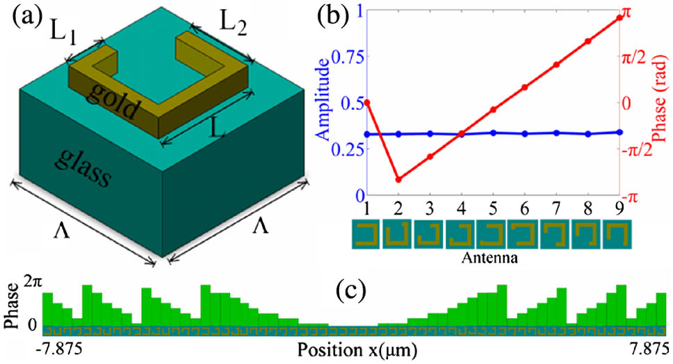
Fig. 1. (a) Sketch of basic MRSRR unit on top of the silica glass substrate, L = 150 nm Λ = 250 nm t = 100 nm L 1 + L 2 = 175 nm x
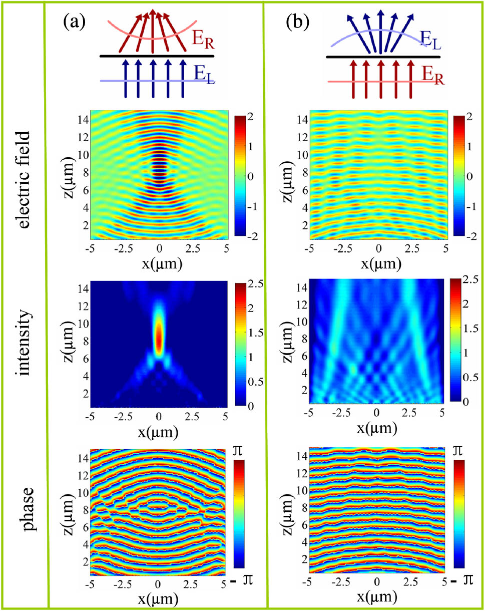
Fig. 2. Full-wave simulations are performed for the propagation of a normally incident CP wave at 808 nm through the MRSRR metalens. (a) The electric field, field intensity, and phase distribution indicate that the metalens is a positive lens for LCP incident light, and (b) shows that the metalens is a negative lens for RCP incident light.
Fig. 3. Intensity distribution of the transmitted RCP light through the designed MRSRR metalenses with different focal lengths of 4.04, 8.08, and 12.12 μm, respectively, on the x – z
Fig. 4. Intensity distribution of the transmitted RCP light through the designed MRSRR metalens on the x – z
Fig. 5. Intensity distribution of the transmitted RCP light for the designed MRSRR metalenses with different NAs of 0.43, 0.53, and 0.71 on the x – z

Set citation alerts for the article
Please enter your email address
© Copyright 2018-2021 | Chinese Laser Press. All Rights Reserved 沪ICP备15018463号-20