
Emiliya Dimova, Andon Rangelov, Elica Kyoseva, "Tunable bandwidth optical rotator," Photonics Res. 3, 177 (2015)
- Photonics Research
- Vol. 3, Issue 4, 177 (2015)
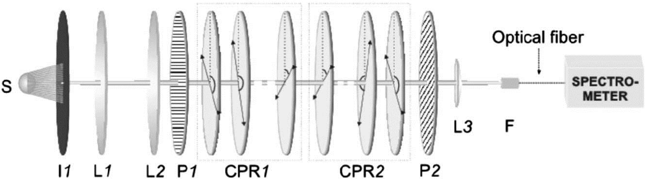
Fig. 1. Experimental setup. The source S I L 1 L 2 P 1 P 2 L 3 F
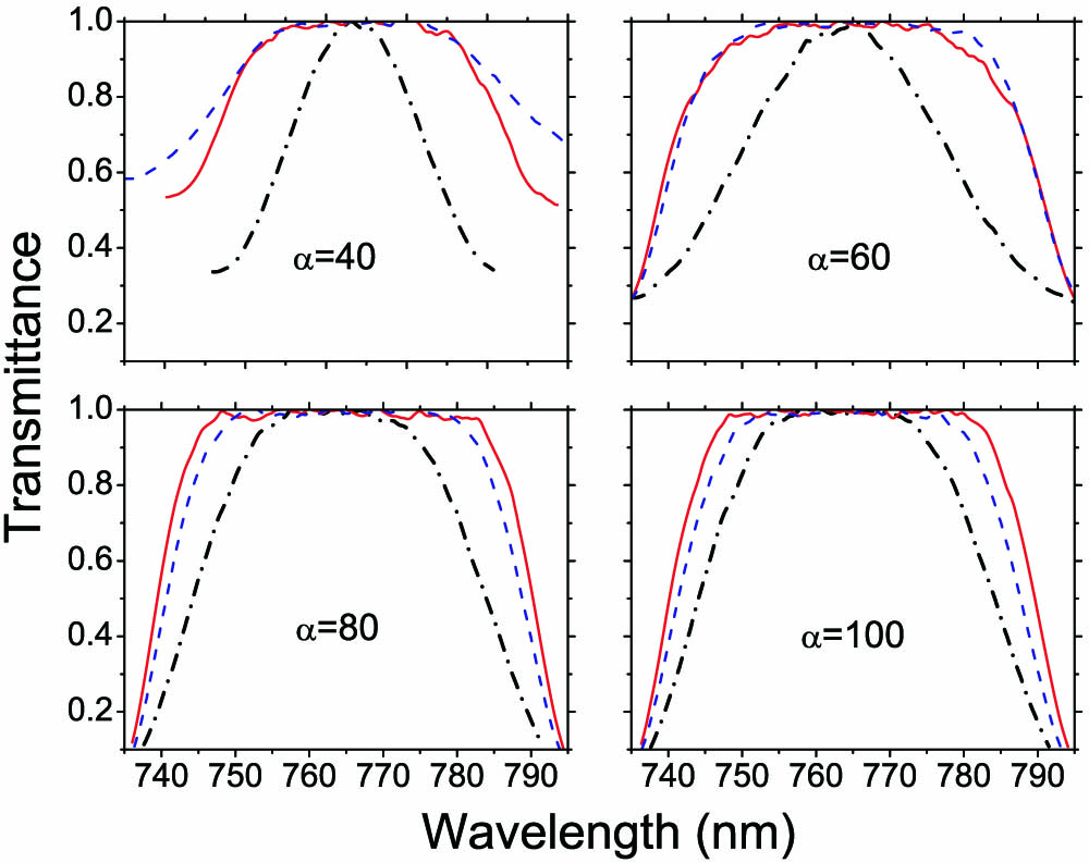
Fig. 2. Measured transmittance for two different composite broadband rotators. The blue dashed line represents a rotator with six half-wave plates, while the red solid line represents a rotator with 10 half-wave plates. The black dash-dotted line represents a rotator comprising two half-wave plates for easy reference.
Fig. 3. Measured transmittance for two different composite narrowband rotators. The blue dashed line represents a rotator with six half-wave plates, while the red solid line represents a rotator with 10 half-wave plates. The black dash-dotted line represents a rotator comprising two half-wave plates for easy reference.
| ||||||||||||||||
Table 1. Calculated Angles (in Degrees) of the Optical Axes of the Individual Half-Wave Plates to Implement Composite Sequences of Broadband and Narrowband Half-Wave Plates


Set citation alerts for the article
Please enter your email address

© Copyright 2018-2021 | Chinese Laser Press. All Rights Reserved 沪ICP备15018463号-20