Abstract
High-repetition-rate (HRR) pulsed fiber lasers have attracted much attention in various fields. To effectively achieve HRR pulses in fiber lasers, dissipative four-wave-mixing mode-locking is a promising method. In this work, we demonstrated an HRR pulsed fiber laser based on a virtually imaged phased array (VIPA), serving as a comb filter. Due to the high spectral resolution and low polarization sensitivity features of VIPA, the 30 GHz pulse with high quality and high stability could be obtained. In the experiments, both the single-waveband and dual-waveband HRR pulses were achieved. Such an HRR pulsed fiber laser could have potential applications in related fields, such as optical communications.As the sources of optical pulses in the picosecond and femtosecond range, ultrafast fiber lasers play important roles in the areas of optical communications, biomedicine, and chemical detection[1,2]. During the developments of ultrafast fiber lasers, shorter pulse duration, higher pulse energy, and larger pulse repetition rate are the main goals for industrial applications. Particularly, the high-repetition-rate (HRR) pulsed fiber laser is the key component in areas of high-capacity telecommunication systems and microwave photonics[3,4]. Generally, the HRR pulse could be achieved by cutting down the length of the laser cavity[5–7] and high-order harmonic mode-locking[8–14]. However, the former has a hard time achieving a pulse train with a higher than 20 GHz repetition rate due to the limited physical cavity length, while the latter is mainly limited by the instability. Fortunately, it has been demonstrated that dissipative four-wave-mixing (DFWM) mode-locking could be employed to easily and effectively generate HRR pulses with repetition rate of even up to tens or hundreds of gigahertz (GHz)[15–25]. As we know, the comb filter is one of the key devices to realize DFWM mode-locking. The fineness of the comb filter greatly affects the HRR pulse quality, and the free spectral range (FSR) of the comb filter determines the pulse repetition rate. So far, several types of comb filters have been utilized in DFWM mode-locked lasers to obtain HRR pulses. In 2013, Mao et al. used a Mach–Zehnder interferometer with variable FSR to obtain repetition-rate tunable HRR pulses[20]. As the multi-wavelength selective components, a Fabry–Perot comb filter was employed, and a 100 GHz pulsed fiber laser was obtained[22]. Recently, the nonlinear micro-cavity and graphene-deposited microfiber knot resonator, that provide the highly nonlinear effect and comb filtering effect at the same time, were demonstrated to be effective for the HRR pulse generation by DFWM mode-locking[19,23]. These successful experimental results motivate us to continue searching for other kinds of comb filters with good performance for DFWM mode-locking.
On the other hand, the virtually imaged phased array (VIPA) is a “side-entrance” Fabry–Perot etalon-structure-based optical spectral disperser[26]. It achieves high spectral dispersion through the interference of multiple reflections between two interfaces of a solid etalon. Therefore, the VIPA also possesses the comb filtering effect. Due to its advantages, including large angular dispersion, low dependence of the input polarization state, and simple structure, the VIPA plays important roles in various areas, i.e., wavelength division multiplexing (WDM), dispersion compensating, and spectroscopy[26–30]. Particularly, because of the high spectral resolution feature of VIPA, it has been employed as the hyperfine wavelength demultiplexer[26,28]. Xiao et al. demonstrated a multi-channel hyperfine wavelength demultiplexer at 1550 nm with the VIPA, whose channel spacing is 24 pm, and the 3 dB channel bandwidth is 6 pm[28]. Then, some questions would naturally arise as to whether the VIPA could act as the comb filter for the DFWM mode-locking, and whether the high spectral resolution and low polarization sensitivity features of VIPA would be beneficial for the high-quality, high-stability HRR pulse generation.
In this work, taking advantage of the high spectral resolution and low polarization sensitivity features of VIPA, an HRR pulse with high quality and high stability was achieved in an Er-doped fiber (EDF) laser. Here, the DFWM mode-locking was realized by the high nonlinear effect of a highly nonlinear fiber (HNLF) and the comb filter effect of VIPA. At appropriate cavity parameters, the HRR pulses at a repetition rate of 30 GHz with good stability were observed in our experiments. The HRR pulse is centered at 1557.31 nm, and the pulse duration is ∼1.19 ps. In addition, through tuning the polarization controller (PC), we can adjust the central wavelength of the HRR pulse continually from 1554.26 nm to 1558.60 nm. Then, utilizing the spectral filter effect of nonlinear polarization rotation (NPR), a dual-waveband HRR pulse could be achieved, whose central wavelengths are 1553.46 nm and 1565.04 nm, respectively. What is more, we also achieved the wavelength switchable operation of dual-wavelength HRR pulses. These results demonstrate that the VIPA is an alternative candidate to act as the comb filter to realize the DFWM mode-locking.
Sign up for Chinese Optics Letters TOC. Get the latest issue of Chinese Optics Letters delivered right to you!Sign up now
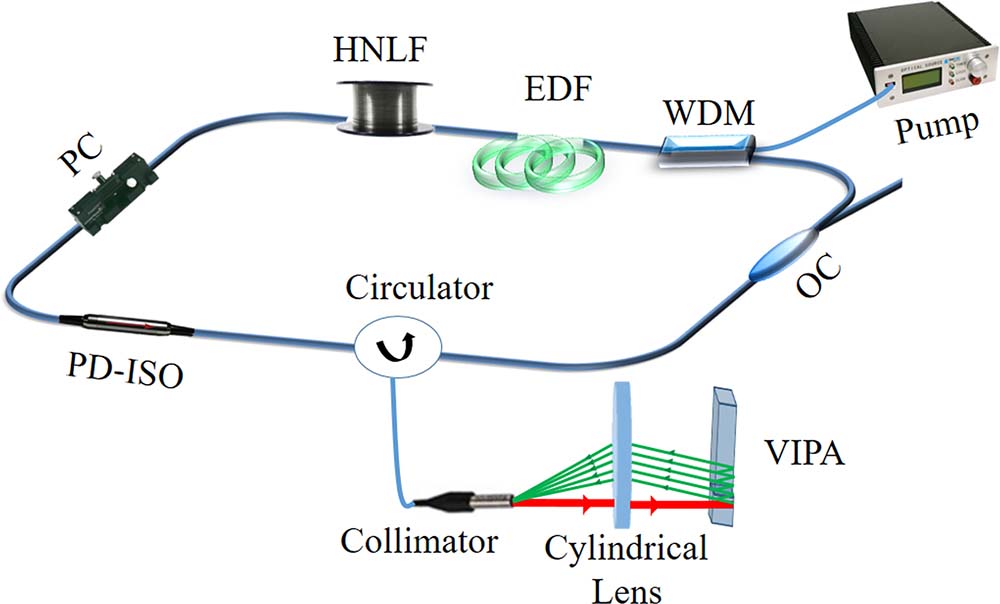
The experimental schematic of the HRR pulsed fiber laser based on VIPA is illustrated in Fig. 1. A ∼15 m EDF serves as the gain medium. The PC is employed to control the polarization state of the light inside the laser cavity. The polarization dependent isolator (PD-ISO) assures the unidirectional operation. In order to provide a high nonlinear effect for the realization of DFWM mode-locking, we used an 85 m long HNLF, where zero dispersion is at 1550 nm. The whole cavity length is ∼104.60 m, corresponding to longitudinal mode interval of ∼1.89 MHz. To investigate the performance of the VIPA on the HRR pulse generation, the collimated light emitted from the circulator is then injected into the entrance window of VIPA through the cylindrical lens (f = 300 mm). The light reflected by the VIPA returns to the laser cavity through the circulator. Here, the VIPA is used as a comb filter, and its FSR is 30 GHz, which determines the pulse repetition rate. The laser output is taken out by a 10:90 optical coupler (OC) and monitored by an optical spectrum analyzer (OSA, Yokogawa AQ6317C) and an autocorrelator (FR-103WS).

Figure 1.Schematic of HRR pulsed fiber laser based on VIPA.
The structure of VIPA is shown in Fig. 2(a). A flat plate has a partially reflective (PR) coating on the right surface and a highly reflective (HR) one on the left surface. There is an entrance window area on the left surface with an anti-reflection (AR) coating strip. Focused by a cylindrical lens, the collimated beam then enters into the window area of the VIPA with a small angle. The input light undergoes plenty of reflections between the two surfaces of the VIPA. Then, the comb filter effect could be achieved via multiple beam interference. The thickness of the plate is 3.371 mm, which determines the FSR of the VIPA (30 GHz). To investigate the spectral response of VIPA, an amplified spontaneous emission light source at 1550 nm was employed. It can be seen in Fig. 2(b) that the spectral interval is ∼0.24 nm, consistent with the VIPA’s FSR (30 GHz), and the modulation depth is ∼10 dB.
Figure 2.(a) Structure of VIPA; (b) spectral response of VIPA. Inset: spectral response in a larger range.
Due to the comb filtering effect of VIPA and the high nonlinear effect of HNLF, the DFWM-mode-locking operation can be realized[15]. When the pump power was increased to 66 mW, and the PC was properly set, the HRR pulse was achieved in the fiber laser based on VIPA. In order to get better laser performance, we increased the pump power to 192 mW. Figure 3 illustrates the output characteristics in this state. In Fig. 3(a), the comb profiles could be observed on the spectrum, and the spectral separation of combs is ∼0.24 nm, determined by the FSR of VIPA. In addition, the completely spectral envelope has a Gaussian shape. These results demonstrated that the fiber laser operated in the DFWM mode-locking regime. The central wavelength and the 3 dB bandwidth of the spectral envelope are 1557.31 nm and 8.09 nm, respectively. The autocorrelation trace shown in Fig. 3(b) indicates that the pulse train with temporal spacing of 33.33 ps is obtained from the fiber laser, corresponding to a pulse repetition rate of 30 GHz, which is consistent with the spectral separation of ∼0.24 nm. If a Gaussian profile is assumed, the pulse duration is estimated as ∼1.19 ps. To verify the stability of the laser output, the spectrum was scanned 20 times at 5 min intervals. It can be seen from Fig. 3(c) that there are no obvious intensity fluctuations and wavelength shifts, indicating great stability. Here, it should be noted that the low polarization sensitivity of VIPA makes a great contribution to the stability. Note that the spectral filtering effect could be induced by the NPR effect, i.e., the combination of PD-ISO and intracavity birefringence, whose wavelength at the transmission peak could be adjusted by rotating the PC[31–33]. Therefore, the single-waveband HRR pulse tunable operation was achieved in our experiments. Figure 3(d) presents that the central wavelength of the HRR pulse is shifted from 1554.26 nm to 1558.60 nm through finely adjusting the PC. The wavelength tuning range of the HRR pulse can be increased through improving the cavity loss. It is important to notice that every HRR pulse operation in Fig. 3(d) is very stable at room temperature.
Figure 3.Single-waveband HRR pulse operation. (a) Optical spectrum; (b) autocorrelation trace; (c) stability measurement; (d) wavelength-tunable operation.
Due to the combination of the two comb filters of NPR and VIPA, the dual-waveband HRR pulse operation was obtained in the experiments by finely tuning the pump power and PCs. Figures 4(a) and 4(b) show the laser performance in the dual-waveband HRR pulse operation with a pump power of 240 mW. The dual-waveband HRR pulse spectrum covers two wavebands, whose central wavelengths are 1553.46 nm and 1565.04 nm, respectively. The spectral interval of two wavebands is 11.58 nm, which could be changed slightly through rotating the PC. The interval of spectral lines is ∼0.24 nm, determined by the VIPA. Figure 4(b) presents the autocorrelation trace with a pulse interval of 33.33 ps, corresponding to the repetition rate of 30 GHz. By precisely tuning the PC to adjust the cavity loss, the wavelength switchable operation of the dual-waveband HRR pulse was obtained and presented in Figs. 4(c)–4(f). The switchable HRR pulses are centered at 1554.27 nm and 1564.47 nm, respectively. Note that there is a small spectral drift of the central positions between the single-waveband and dual-waveband regimes, which could be owing to the shift of the central wavelength of the NPR spectral filter by rotating the PC. In addition, the lasing lines in the single-waveband HRR pulse state are more than that of each waveband in the dual-waveband HRR pulse state because of the same pump power of 240 mW. As for the time domain, Figs. 4(d) and 4(f) show the corresponding autocorrelation traces at 1554.27 nm and 1564.47 nm, respectively. Both repetition rates at the two wavebands are 30 GHz. Here, we can see that the autocorrelation trace in Fig. 4(d) presents higher pulse quality than that of Figs. 4(b) and 4(f). Since the autocorrelator operates in the averaged mode, the autocorrelation trace of the dual-waveband HRR pulse could be regarded as the averaged result of each waveband HRR pulse. Therefore, the pulse quality of the dual-waveband HRR pulse was pulled down.
Figure 4.Dual-waveband HRR pulse operation. (a) Dual-waveband HRR pulse spectrum; (b) corresponding autocorrelation trace of dual-waveband HRR pulse; (c) and (e) switchable spectra; (d) and (f) corresponding autocorrelation traces.
In this work, single-waveband and dual-waveband HRR pulses were achieved in an EDF laser based on VIPA. We can see that the noise level of the autocorrelation trace is a little high, which could be attributed to the supermode noise induced by the too many longitudinal modes in a single lasing line[34–37]. On the other hand, the supermode noise is also the reason for the phenomenon where the intensities of the peaks on autocorrelation traces decrease from the center to the sides[17], which indicates that there is intensity modulation with a larger time range. However, no intensity fluctuation could be observed on the oscilloscope in the experiments. Therefore, the results confirm that the laser operates in the HRR pulse state with supermode noise rather than a low-repetition-rate pulsed state, where each pulse has a substructure (a pulse burst) with smaller time features. For the purpose of suppressing the supermode noise and improving the quality of HRR pulses, it is effective to shorten the cavity length, such as substituting for the long HNLF by a graphene-deposited microfiber photonic device[22] or inserting a subcavity into the main laser cavity. It should be noted that since the repetition rate of the HRR pulse is determined by the FSR of VIPA, pulses with repetition rates higher than 100 GHz could also be achieved by using the VIPA with an FSR of higher than 100 GHz[38]. For the DFWM mode-locking, the pump power is one of the critical parameters. Zhao et al. have verified that if the fiber laser operated at a higher pump power, the HRR soliton molecules could be obtained in a fiber laser[39]. Then, it would be of great significance to systematically study the impact of pump power on the performance of the HRR pulse. Moreover, taking the importance of cavity dispersion into consideration, it is necessary to conduct more experiments to study how the different cavity dispersion affects the HRR pulse quality.
In summary, taking advantage of the high spectral resolution and low polarization sensitivity of VIPA, we demonstrate the generation of a high-quality 30 GHz HRR pulse in an EDF laser based on VIPA. Through finely adjusting the PC, we could continuously adjust the central position of a single-waveband HRR pulse. In addition, together with the comb filtering effects of NPR and VIPA, we also obtained the dual-waveband HRR pulse and the wavelength switchable operation. As expected, the VIPA could be employed as an alternative candidate of comb filters for the DFWM mode-locking operation. What is more, the 30 GHz HRR pulse could find potential applications in high-speed optical communications.
References
[1] U. Keller. Nature, 424, 831(2003).
[2] M. E. Fermann, I. Hartl. IEEE J. Sel. Top. Quantum Electron, 15, 191(2009).
[3] D. Cotter, R. J. Manning, K. J. Blow, A. D. Ellis, A. E. Kelly, D. Nesset, I. D. Phillips, A. J. Poustie, D. C. Rogers. Science, 286, 1523(1999).
[4] Z. Y. Zhang, A. E. H. Oehler, B. Resan, S. Kurmulis, K. J. Zhou, Q. Wang, M. Mangold, T. Suedmeyer, U. Keller, K. J. Weingarten, R. A. Hogg. Sci. Rep., 2, 477(2012).
[5] A. Martinez, S. Yamashita. Opt. Express, 19, 6155(2011).
[6] A. Martinez, S. Yamashita. Appl. Phys. Lett., 101, 041118(2012).
[7] W. Wang, W. Lin, H. Cheng, Y. Zhou, T. Qiao, Y. Liu, P. Ma, S. Zhou, Z. Yang. Opt. Express, 27, 10438(2019).
[8] D. Panasenko, P. Polynkin, A. Polynkin, J. V. Moloney, M. Mansuripur, N. Peyghambarian. IEEE Photonic. Tech. Lett, 18, 853(2006).
[9] K. Jiang, S. N. Fu, P. Shum, C. Lin. IEEE Photon. Tech. Lett, 22, 754(2010).
[10] G. Sobon, K. Krzempek, P. Kaczmarek, K. M. Abramski, M. Nikodem. Opt. Commun., 284, 4203(2011).
[11] Z. C. Luo, M. Liu, H. Liu, X. W. Zheng, A. P. Luo, C. J. Zhao, H. Zhang, S. C. Wen, W. C. Xu. Opt. Lett., 38, 5212(2013).
[12] Q. Q. Huang, T. X. Wang, C. H. Zou, M. AlAraimi, A. Rozhin, C. B. Mou. Chin. Opt. Lett., 16, 020019(2018).
[13] M. Liu, A. P. Luo, W. C. Xu, Z. C. Luo. Chin. Opt. Lett., 16, 020008(2018).
[14] Q. Huang, Z. Huang, M. Al Araimi, A. Rozhin, C. Mou. IEEE Photon. Tech. Lett, 32, 121(2020).
[15] M. Quiroga-Teixeiro, C. B. Clausen, M. P. Sørensen, P. L. Christiansen, P. A. Andrekson. J. Opt. Soc. Am. B, 15, 1315(1998).
[16] S. M. Zhang, F. Y. Lu, X. Y. Dong, P. Shum, X. F. Yang, X. Q. Zhou, Y. D. Gong, C. Lu. Opt. Lett., 30, 2852(2005).
[17] J. Schröder, S. Coen, F. Vanholsbeeck, T. Sylvestre. Opt. Lett., 31, 3489(2006).
[18] J. Schröder, T. D. Vo, B. J. Eggleton. Opt. Lett., 34, 3902(2009).
[19] M. Peccianti, A. Pasquazi, Y. Park, B. E. Little, S. T. Chu, D. J. Moss, R. Morandotti. Nat. Commun., 3, 765(2012).
[20] D. Mao, X. Liu, Z. Sun, H. Lu, D. Han, G. Wang, F. Wang. Sci. Rep., 3, 3223(2013).
[21] S. S. Jyu, L. G. Yang, C. Y. Wong, C. H. Yeh, C. W. Chow, H. K. Tsang, Y. Lai. IEEE Photonics J., 5, 1502107(2013).
[22] Y. L. Qi, H. Liu, H. Cui, Y. Q. Huang, Q. Y. Ning, M. Liu, Z. C. Luo, A. P. Luo, W. C. Xu. Opt. Express, 23, 17720(2015).
[23] M. Liu, R. Tang, A. P. Luo, W. C. Xu, Z. C. Luo. Photon. Res., 6, C1(2018).
[24] H. Bao, A. Cooper, M. Rowley, L. D. Lauro, J. S. T. Gongora, S. T. Chu, B. E. Little, G. L. Oppo, R. Morandotti, D. J. Moss, B. Wetzel, M. Peccianti, A. Pasquazi. Nat. Photon., 13, 384(2019).
[25] Z. X. Ding, Z. N. Huang, Y. Chen, C. B. Mou, Y. Q. Lu, F. Xu. Adv. Photon., 2, 026002(2020).
[26] M. Shirasaki. Opt. Lett., 21, 366(1996).
[27] M. Shirasaki. IEEE Photon. Tech. Lett, 9, 1598(1997).
[28] S. Xiao, A. M. Weiner. IEEE Photon. Tech. Lett, 17, 372(2005).
[29] V. R. Supradeepa, C. B. Huang, D. E. Leaird, A. M. Weiner. Opt. Express, 16, 11878(2008).
[30] L. Nugent-Glandorf, T. Neely, F. Adler, A. J. Fleisher, K. C. Cossel, B. Bjork, T. Dinneen, S. A. Diddams. Opt. Lett., 37, 3285(2012).
[31] W. S. Man, H. Y. Tam, M. S. Demokan, P. K. A. Wai, D. Y. Tang. J. Opt. Soc. Am. B, 17, 28(2000).
[32] Z. C. Luo, A. P. Luo, W. C. Xu, H. S. Yin, J. R. Liu, Q. Ye, Z. J. Fang. IEEE Photonics J., 2, 571(2010).
[33] H. Zhang, D. Y. Tang, R. J. Knize, L. M. Zhao, Q. L. Bao, K. P. Loh. Appl. Phys. Lett., 96, 111112(2010).
[34] A. Pasquazi, M. Peccianti, B. E. Little, S. T. Chu, D. J. Moss, R. Morandotti. Opt. Express, 20, 27355(2012).
[35] M. Nakazawa, K. Tamura, E. Yoshida. Electron. Lett., 32, 461(1996).
[36] E. Yoshida, M. Nakazawa. Opt. Lett., 22, 1409(1997).
[37] J. Schröder, D. Alasia, T. Sylvestre, S. Coen. J. Opt. Soc. Am. B, 25, 1178(2008).
[38] A. J. Metcalf, V. T. Company, V.R. Supradeepa, D. E. Leaird, A. M. Weiner. Opt. Express, 21, 28029(2013).
[39] L. M. Zhao, D. Y. Tang, D. Liu. Appl. Phys. B, 99, 441(2010).