Di Wang, Qionghua Wang, Chuan Shen, Xin Zhou, Chao Liu. Color holographic zoom system based on a liquid lens[J]. Chinese Optics Letters, 2015, 13(7): 072301
Copy Citation Text
In this Letter, we propose a color holographic zoom system based on a liquid lens. We use the spatial multiplexing method to realize color reconstruction. By controlling the focal lengths of the liquid lens and the encoded digital lens on the spatial light modulator panel, we can change the magnification of the reconstructed image very quickly, without mechanical parts and keeping the output plane stationary.
As an ideal three-dimensional (3D) display technology[1–4], holographic display records and reproduces all light field information, which includes the amplitude and phase in the form of a fringe pattern generated by interfering with a reference beam. In order to adjust the magnification of the reconstructed image, some scholars have proposed a lens-less zoomable holographic projection using scaled Fresnel diffraction[5]. By calculating diffraction at different sampling rates on a projected image and hologram, they can realize the zoom function. In addition, the active optical components such as a liquid lens and liquid-crystal lens also have been widely used in zoom systems[6–13]. Various methods to achieve color holographic display have been proposed, such as using the time-division method and space-division method[14–17]. Since a hologram is based on interference with a reference beam, the light wavelength must be fixed, and a color holographic system requires multiple holograms with different wavelengths. Consequently, the system becomes larger and more complex, and it is challenging to realize color holographic zoom. Recently, a digital lens has been widely used in holographic systems. Compared to a Fourier lens, a digital lens acts on an active area of the spatial light modulator (SLM), whereas diffraction beams caused by the pixelated structure of the SLM are not modulated. However, due to its programmability, the focal length can be changed easily. By programming the digital lens, it can be used as a zoom lens, which renders the system more compact. In this Letter, we propose a color holographic zoom system based on a liquid lens. By controlling the focal lengths of the liquid lens and the encoded digital lens on the SLM panel, we can change the magnification of the reconstructed image very quickly, without mechanical parts and keeping the output plane stationary.
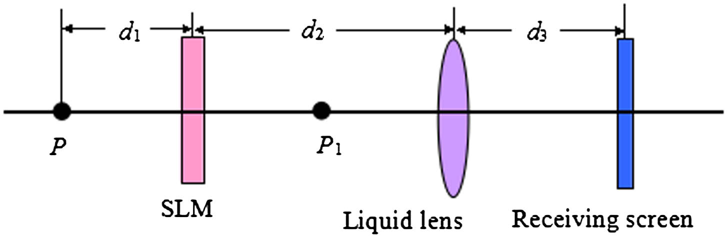
An analysis of zoom modules in our holographic zoom system is shown in Fig. 1. is the light source, is the image location after the SLM, the receiving screen is the image location after the liquid lens, is the distance between the SLM and the light source, is the distance between the SLM and the liquid lens, is the distance between the liquid lens and the receiving screen, is the focal length of the digital lens encoded on the SLM, and is the focal length of the liquid lens. In our system, the light source is collimated, so equals infinity.
Figure 1.Zoom modules of the holographic zoom system.
The lens has the effect of phase transformation, and its phase modulation can be described as[18]where and are the coordinates measured from the center of the lens, is the focal length of the lens, and is the wavelength of the incident light. In order to achieve the function of digital lens using the SLM, the phase distribution of the phase modulation diagram on the SLM needs to satisfy Eq. (1). We calculate the phases of the object and the digital lens, respectively, and add them together to obtain a new phase hologram. The new phase can be expressed as follows where is the phase of the object on the hologram. Terms and satisfy Eq. (2) when the phase is 0 or π. We set behind the SLM, the distance between the SLM and is . According to diffraction theory, the complex amplitude distribution at is[16]where is the complex amplitude distribution on the hologram; , is the coordinate distribution on the hologram. In holographic reconstruction we know that , where is the pixel pitch of the SLM, is the focal length of the Fourier lens, and is the size of reconstructed image at the focal length of the Fourier lens. Here we use the digital lens to replace the Fourier lens. Term locates at the focal plane of digital lens, so the reconstructed image size at can be expressed as . The object position of the liquid lens is , and the image position of the liquid lens satisfies From Eq. (4), we can see that when the receiving screen, SLM, and liquid lens remain stationary, the value of is determined by . The lateral magnification of the liquid lens is , so the size of the reconstructed image on the screen is
Sign up for Chinese Optics Letters TOC. Get the latest issue of Chinese Optics Letters delivered right to you!Sign up now
Since , , and remain constant, we define the magnification of the system as follows
The structure of the liquid lens is shown in Fig. 2. Two immiscible liquids employed in our device are a transparent oil (Liquid 1) and a conducting droplet (Liquid 2). The substrate is patterned with electrodes, and four rectangular indium–tin oxide (ITO) glass sheets coated with Teflon and SU8 are assembled to form the side wall. The relationship between the contact angle and the applied voltage can be described by[19]where is the contact angle when voltage is applied to the device, is the thickness of the dielectric insulator, is the dielectric constant of the dielectric insulator, is interfacial tension between the sidewall and Liquid 1, is interfacial tension between the sidewall and Liquid 2, is the surface tension between the two liquids, and is the voltage applied to the electrode.
In the voltage-off state, the liquid–liquid interface bends upwards and the lens is diverging. When we apply a continuous voltage to the device, the surface can be changed due to the electrowetting effect. When the applied voltage exceeds a critical value, the interface bends downwards and the lens begin to converge. By changing the voltage applied to the electrode, we can change the focal length of the liquid lens.
In the proposed holographic zoom system, we can adjust the focal length of the digital lens that is loading to the SLM and the liquid lens. In accordance with Eqs. (5) and (6), we can adjust the magnification of the reconstructed image without moving their locations.
Figure 3 shows the structure of the color holographic zoom system consisting of a red laser (), a green laser (), a blue laser (), three filters, three lenses, three beam splitters (BSs), a computer, a SLM, a liquid lens, and a receiving screen. A laser, a filter, and a lens are used to generate a collimated light source. We use the space-division method to realize the color reconstruction[16]. Three collimated light wavelengths each irradiate one-third of the area of the SLM. Then the color reconstructed images pass through the liquid lens, and three colors are recombined on the receiving screen so we can see the color results on the receiving screen. We used a reflective SLM, and its resolution is with a pixel pitch of 8 μm. A liquid lens is placed behind the SLM with an aperture of 3.5 mm. The distance between the SLM and the liquid lens is 15 cm, and the screen is fixed behind the liquid lens at 30 cm.
Figure 3.Structure of the color holographic zoom system.
When a voltage is applied to the liquid lens continuously, the focal length of the lens changes accordingly. Figure 4 gives the measured voltage-dependent focal length of the liquid lens; the focal length of the liquid lens can range from 5 cm to infinity, and the focal length of the liquid lens varies with the wavelength of the laser and the voltage applied to the liquid lens. When the voltage is applied to the liquid lens, the focal length for the red color is the largest, then the green color, and the blue color is the smallest. In other words, the focal length increases with the wavelength of the laser.
Figure 4.Relationship between the voltage and focal length of the liquid lens.
We process the color separation of the original object for red (r), green (g), and blue (b) components using computer graphics. Here we use a Gerchberg–Saxton (GS) algorithm to generate the hologram[16,20]. Figure 5(a) is the original object and Fig. 5(b) is the hologram of the red color scene. Then a digital lens is generated according to Eq. (2). Figure 5(c) is the hologram of the digital lens with focal length . We add the phase of the digital lens to the phase distribution of the image according to Eq. (2) and a new hologram can be generated, as shown in Fig. 5(d). With this method, we process the other two color holograms and generate two new holograms. The green hologram is combined with the digital lens of focal length and the blue hologram is combined with the digital lens of focal length . Then three new color holograms are loaded on the SLM and each occupies one-third of the area of the SLM.
Figure 5.Process of the holograms: (a) original object; (b) hologram of the red color scene; (c) hologram of the digital lens; (d) combined hologram.
We input the corresponding parameters into Eq. (4), and we obtain and . According to Eqs. (4)–(6), we can obtain the following When is given, we can obtain from Eq. (8), and a desired reconstructed image can be seen on the screen. Figure 6 are the reconstructed results of the monochrome scenes.
Figure 6.Reconstructed results of the monochrome scenes: (a) red scene; (b) green scene; (c) blue scene.
When a voltage is applied to the liquid lens, we can obtain the focal length of the liquid lens for r, g, b according to Fig. 4. Then we can obtain a uniform for each color simultaneously according to Eq. (8). We record the focal length as , , and for the red, green, and blue light, respectively. When the voltage changes, the focal lengths , , and change correspondingly. Then the focal lengths of the digital lenses , , and for the red, green, and blue color holograms can be calculated correspondingly according to Eq. (8). When a voltage is applied to the liquid lens, we can obtain the magnification for three color wavelengths according to Eq. (9). The system has different magnifications for different colors, which can be expressed as follows where , , and are the magnification for the red, green, and blue color images, respectively. In order to obtain a uniform magnification, we can process three color input bitmaps in proportion to superpose a color image. Figures 7 and 8 show the color reconstructed results, and the results show that the images can be zoomed. The size of the reconstructed images can also be calculated according to Eq. (5). We use green color as the standard; when , is , as shown in Fig. 7(b); when , is , as shown in Fig. 7(e). We can see the full images from Figs. 7(a)–7(d). When the voltage applied to the liquid lens changes, the aperture changes correspondingly, and consequently we can only see part of the image because of the small aperture of the liquid lens from Fig. 7(e).
Figure 7.Results of the color holographic zoom system: (a) ; (b) ; (c) ; (d) ; (e) .
We use the green laser as an example and record the focal length and when the contrast ratio of the captured image is at the maximum. From Eq. (8) we know . From this we know the relationship between the liquid lens and the digital lens is an inverse function. When , the focal length of the liquid lens increases as the focal length of the SLM increases, and the liquid lens is used as a negative lens. When , the focal length of liquid lens decreases as the focal length of the SLM increases, and the liquid lens is used as a positive lens. Figure 9 is the curve when , where the focal length of the SLM represents the focal length of the digital lens, and F represents the focal length of the liquid lens. The blue and red lines represent the calculated and experimental results, respectively. From the results we can see that decreases with . When trends to infinity, is about 30 cm. The experimental and theoretical results are consistent with each other. By measuring the change of the width of the image, we can measure the magnification . When , is measured to be 2.5; when increases to , we know can be close to 1 from Eq. (10). Figure 10 shows the results of changes in with the digital lens (F/SLM represents the focal length of the digital lens).
Figure 9.Relationship between the digital lens and the liquid lens.
Compared to the reported system, the proposed system has certain advantages. For example, the reported zoom system that uses one SLM is based on a scaled diffraction calculation. By changing the sampling rate on the projected image, the system can realize a zoomable projection. The system is compact and simple, but speckle noise exists in the reconstructed image, which may affect the viewing experience. Compared to it, our proposed system is based on a digital lens and a liquid lens, which contains all information of the object, so it can realize a desired zoomable projection, and color reconstruction has been also realized. Compared to a liquid-crystal lens, the voltage applied to the liquid lens is higher. However, the liquid lens has a higher light efficiency and optical power. The cost is less and the production process is easier. Moreover, the requirements of the liquid-crystal lens are very stringent in terms of the incident light angle, whereas the liquid lens has no requirements on it. The aberration of the liquid lens can be estimated as follows. First, when the density of the two liquids does not match, distortion of the liquid surface may occur due to the gravity effect, then a coma appears. In our work, the liquid density difference is very small, so the coma is very small. Second, the curvature of the electrowetting liquid lens can be seen as an ideal sphere, so the liquid lens will have an aberration in a similar manner as the conventional lens. The proposed system still has some unsolved issues. For example, in order to obtain the color results, we divide the SLM into three parts, and consequently the quality of the reconstructed color image decreases. This can be improved by using multiple SLMs. When decreases, the digital lens has a higher spatial frequency. Consequently, we set the minimum value of the digital lens to be 25 cm according to the Nyquist sampling theorem. In addition, the liquid lens may have an influence on the quality of the image. When light passes through the liquid lens, much energy is lost, which may affect the quality of the results. When the magnification increases, the small aperture of the liquid lens may limit the size of the image, and consequently we can only see part of the object, as shown in Fig. 7(e). The vignetting effect on the aperture size caused by the liquid lens may also affect the results, and consequently the off-axis image point may become dark. For this, we can reduce the distance between the and the liquid lens by adjusting the focal length of the digital lens; a liquid lens with a larger aperture can also be produced to reduce vignetting. The response time of our liquid lens is , whereas for holographic video applications, the frames must be updated at least at 25 fps. We can reduce the thickness of the insulating layer or choose a dielectric layer with a high dielectric to improve its response time, and it can be applied to the holographic video. In future work, we will try to solve these problems, which can improve our system.
We propose a color holographic zoom system based on a liquid lens. By controlling the focal lengths of the liquid lens and the encoded digital lens on the SLM, we can change the magnification of the reconstructed image very quickly, without mechanical parts and keeping the output plane stationary. The magnification can increase from 1 to 2.5 times when the focal length of the liquid lens and the encoded lens on the SLM change, respectively. In summary, the proposed system is simple and flexible, and therefore has wide applications in holographic displays.
Di Wang, Qionghua Wang, Chuan Shen, Xin Zhou, Chao Liu. Color holographic zoom system based on a liquid lens[J]. Chinese Optics Letters, 2015, 13(7): 072301