A dual optical time domain reflectometry (OTDR) system, which employs two different continuous waves at the optical line terminal and a pair of fiber Bragg gratings at the end of each optical network unit, is proposed in a time-division multiplexing passive optical network (PON). The proposed scheme accomplishes the fiber fault monitoring by comparing the different wavelength’s testing curves. Complete complementary code is utilized to measure multiple wavelength signals simultaneously with only one receiver and to improve the dynamic range of this system. The PON system consisting of 20 km feeding fiber and a 1:16 splitter is investigated by the experiments. The experimental results show that the faulty branch can be successfully identified by using our scheme. What is more, we also demonstrate that our scheme can be applied to the multi-stage PON.
A passive optical network (PON) is considered to be the best choice in accessing solutions to provide high capacity and good services[1–3]. As reported, the majority of operation and maintenance expenses are monitoring fiber links[4,5]. As a consequence, the research for a practical and effective monitoring scheme is essential. Conventional optical time domain reflectometry (OTDR) has been widely used as an indispensable tool to characterize a fiber link in point-to-point (P2P) technologies[6]. Besides, OTDR is also used to measure the vibrations[7]. Whereas it is ineffective in point-to-multipoint infrastructures, especially in tree-structured time-division multiplexing (TDM) PON[8–10], where all the reflections are added up together at the optical line terminal (OLT), thereby, the identification of the faulty branch is the main problem.
Several modified OTDR proposals have been reported to overcome the aforementioned limits[11–14]. A remote fiber test system with out-of-band reflectors installed at each branch can successfully monitor the fiber link of each branch, but the length of each branch is required to be different, and a high-resolution OTDR is also required[11]. Using the correlation between the measured traces and premeasured traces was reported Ref. [12], but this solution is unsuitable for the PON consisting of a large amount of subscribers regardless of the poor resolution. The multi-wavelength OTDR[13], where one wavelength is assigned to one branch, has been reported with the ability to identify the special broken branch. However, it is impractical for a high-capacity PON due to the limited spectrum and high cost. A Brillouin OTDR utilizing Brillouin frequency shift fibers as drop fibers to characterize each branch was reported by Honda[14]. However, this solution increases the cost and the complexity of PON infrastructure. Other than the OTDR-based schemes, optical code (OC)-based methods have been suggested to identify the faulty fiber in a high-capacity PON[15–17]. A modified optical coding scheme by using periodic code (PC) encoders was reported in Ref. [15] for monitoring a large number of subscribers, whereas this scheme would lead to large loss because of the partial reflection and poor correlation characteristics. The scheme of using incrementally pulse-positioned coding (IPPC) to improve the performance of the PC encoder was reported Ref. [16], nevertheless, the receiver becomes more complex. The performance of the aforementioned OC-based PON monitoring technique is affected by the geographical distribution[18] and free of the ability of locating the exact fault within the feeding fiber.
An ideal PON monitoring system should have the ability to identify the special faulty branch, and can also locate the exact fault location within the feeding fiber with good resolution performance. Refer to the standardized requirements related to PON monitoring provided in ITU-T L.310; the monitoring system should also be applied to the single-stage and the multi-stage configurations.
Sign up for Chinese Optics Letters TOC. Get the latest issue of Chinese Optics Letters delivered right to you!Sign up now
In this Letter, we propose a practical code division multiplex (CDM)-based dual-OTDR system for fiber fault monitoring, which employs two distributed feedback (DFB) lasers at the OLT and a pair of fiber Bragg gratings (FBGs) at the end of each branch. Two reflections should be reflected by a pair of FBGs at different wavelengths and distances. Compared with the previous measurements that are stored on the situation when all the branches are well connected, the absence of the two reflections will indicate the special broken branch. In addition, complete complementary code (CCC) is utilized to improve the dynamic range (DR) of the system to support more subscribers and a longer transmission distance. What is more, this scheme can measure two wavelengths simultaneously with only one receiver due to the ideal autocorrelation and cross-correlation of the CCC. The experiments are demonstrated to identify the faulty branch and monitor a two-stage PON. In addition, the measurement results are displayed and discussed.
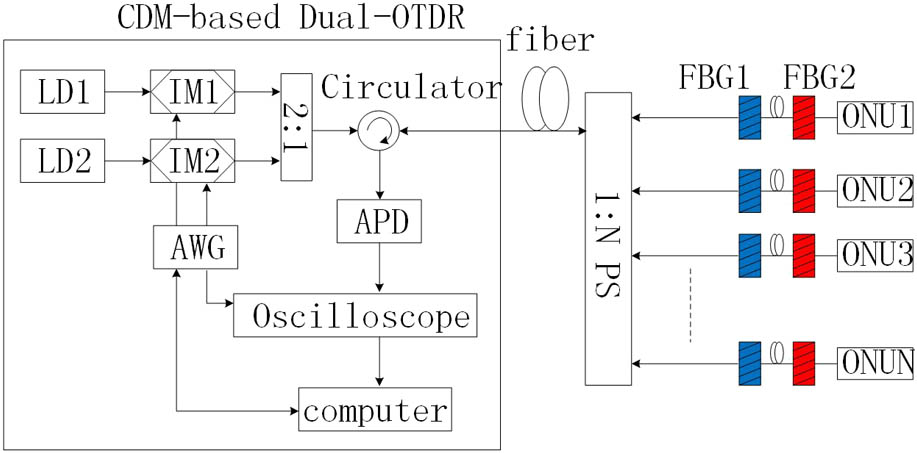
Figure 1 illustrates the principle of a CDM-based dual-OTDR system for centralized monitoring in a TDM-PON, employing a pair of FBGs, which are installed at the end of each branch. Two U-band DFB lasers are separately modulated by two intensity modulators to generate probe signals. The signals are transmitted to the feeding fiber via a coupler and a circulator, and then allocated by a following power splitter (PS) to all branches. The signals reflected by the FBGs are received by the avalanche photodiode (APD). The oscilloscope is triggered by an arbitrary waveform generator (AWG) to acquire the electrical signal from the APD. In the process, CCC is generated by software and spreads to the AWG. At last, the received coded OTDR traces are processed in software to recover the common OTDR traces.
Figure 1.Principle of a CDM-based dual-OTDR system. LD, laser diode; IM, intensity modulator.
In the system, each pair of FBGs is connected by a short fiber whose length is defined as . The is required to be unique so as to distinguish the faulty branch, assuming that the subscribers are installed in a random order. What is more, is set to be 0, which means that two FBGs are directly connected. Considering the resolution of the system, is set to be 3. The unit of is a meter, which is related to the spatial resolution of this monitoring system. Besides, should satisfy the following condition:
Through Eq. (1), we can indicate the fiber length of each subscriber. The primary mission in a fiber fault monitoring system is to distinguish a special faulty branch from all of the branches of a PON in time. Comparing the real-time traces of the fiber with the previously obtained traces from a normal system, we can clearly distinguish the faulty branch through the absence or degradation of the reflection peaks.
Taking four subscribers for example, as illustrated in Fig. 2(a), each subscriber contains two FBGs whose central wavelengths are , , and are 0, 3, 7, and 12 m, respectively. Figure 2(b) shows the traces that are obtained during the system installation in a healthy condition. Figure 2(c) shows the current traces of the PON to be tested in an unhealthy condition. Comparing Fig. 2(c) with Fig. 2(b), the second peak degrades at , and the first peak disappears at . Furthermore, these two peaks locate at the same position corresponding to subscriber I. As a consequence, we can conclude that there is a broken branch, and the broken branch is subscriber I.
Figure 2.Principle for identifying the faulty branch.
In addition, when the fault occurs within the feeding fiber, taking an interruption, for example, all of the reflection peaks are missing, the measure process of this scheme is the same as that of the conventional OTDR in the situation of P2P. Therefore, we can also accomplish the fault location within the feeding fiber. The fault location for the feeding fiber and the ability to identify the faulty subscriber are necessary for a TDM-PON. As a consequence, this scheme can satisfy the requirements of PON monitoring.
What is more, our scheme is also practical for a two-stage PON configuration. Figure 3 illustrates a two-stage network that consists of a 1:8 first stage splitter and 1:32 second stage splitters. The first stage splitter is connected to the second stage splitters via the interfibers. Therefore, the fiber fault would occur within the feeding fiber, interfibers, or drop fibers in a real system. For such a network, two probe wavelengths are assigned to each second splitter. That is to say, the monitoring scheme for a network supporting 256 users requires 16 wavelengths, as shown in Fig. 3. Considering that the lasers are installed at the OLT, the cost of lasers will be averaged by all of the subscribers, so the scheme is cost-effective. In fact, the scheme is through both wavelengths and in order to monitor the PON system. The wavelengths divide all of the subscribers into several sets containing several subscribers, the is used to distinguish the faulty fiber corresponding to one set. When the fault occurs in the feeding fiber, all of the reflection peaks disappear or degrade. At the moment, we can make out the fault location within the feeding fiber as the basic ability of the OTDR technique. By contrast, if the fault occurs in the interfiber, only the reflection peaks corresponding to the two wavelengths that are assigned to the second splitter vanish or decrease. Therefore, the proposed scheme can be applied to different PON structures and to support large subscribers.
Besides the drop fiber differentiation problems, the high splitting loss is also a challenge that must be considered. Although increasing the pulse width can improve the DR, it leads to the degradation of the spatial resolution. Taking into account the tradeoff between the DR and resolution, the duration of the pulse is set to be 10 ns. In order to support higher splitting factors and longer transmission distance, several coding schemes have been proposed[19–21]. The CCC is a sequence set that contains sets of sequences having ideal autocorrelation and cross-correlation properties[22]. Suppose a collection of sequence sets, each of which contains finite length sequences of length . A sequence of CCC can be defined as where is the code length, and is the number of codes in a set of sequence sets. The sum of correlation functions can be expressed as
Bipolar codes that can’t be used in the transmission system need to be converted to unipolar codes. The unipolar codes related to the bipolar codes can be simply expressed as follows:
Each sequence set is assigned to each wavelength. For a wavelength measurement, the unipolar codes and are sent one after another while storing the measurement results after each code is sent. According to the Eq. (3), we can obtain the conventional OTDR traces.
The CCC coding gain can be expressed as
Assuming that the measurements of the conventional and CCC-based OTDR are the same (taking two wavelengths into account), the CCC gain about the improvement of the signal-to-noise ratio (SNR) can be expressed as
As a proof-of-concept, we used C-band components instead of U-band components in the experiment. The structure of the CDM-based dual-OTDR system was the same as illustrated in Fig. 1. Two DFB laser sources with the wavelengths of 1545 and 1550 nm were utilized, and the launch power at the fiber input was below 0 dBm. The duration of the pulse was chosen as 10 ns, which indicated that the resolution of this system is 1 m. In addition, as displayed in Fig. 4, we set up a TDM-PON system with 20 km feeding fiber followed by a 1:16 PS, where only four ports of the PS were used and all of the others were terminated by angled physical contact (APC) connecters. The FBGs installed at the end of each branch provided a reflectance of about 75% to 90% (99% would be the best) within a 3 dB bandwidth of approximately 0.3 nm.
In order to investigate the performance of the proposed scheme, we carried out an experiment in which subscriber I and subscriber II were placed at the same distance from PS on purpose. The lengths of the drop fibers were set to be 1, 1, 5, and 7 m, respectively. The maximum different length of the four drop fibers was 6 m. Corresponding to the four drop fibers, the fiber lengths inserted between two FBGs were 0, 3, 7, and 12 m in order. In fact, even if we directly connect the FBGs without fiber, the reflection peaks corresponding to one branch do not locate at the same location, owing to the pigtail of the FBG itself. In our experiment, the reflection peaks between two FBGs were 6, 9, 13, and 18 m, respectively.
In addition, a two-stage PON consisting of two PSs cascaded together was also set up, as illustrated in Fig. 5, to demonstrate the practical application in such a network. Because of the limitation of the experimental condition, we only measured the situation where the fault occurred in the interfiber.
The measurements are carried out on two wavelengths with a code length of 16 bits. Each of the unipolar measurements are averaged as 4096. The measurements results with the CCC applied are shown in Fig. 6. The solid lines represent the reflection peaks of all four pairs of FBGs when all four subscribers are well connected. The vertical dotted lines indicate the locations of the FBGs. Although the reflections of 1545 nm at 20.013 km are superposed, subscriber I and subscriber II can be distinguished through the reflections of 1550 nm due to the second FBG in each pair of FBGs. In addition, the reflections of subscribers III and IV at 1545 nm can be clearly distinguished, which shows that the resolution of reflective events is less than 2 m in this system. Compared to the solid lines, the dotted lines indicate that the reflection amplitude at 1545 nm corresponding to 20.013 km is decreased, and the reflection at 1550 nm corresponding to 20.019 km is missing. The vertical spacing between these two variable reflections is 6 m, which corresponds to subscriber I. It is obvious that subscriber I is the fault branch. The results demonstrate that this scheme has the ability to identify the special broken branch when the subscribers are located at the same distance. In the experiment, the loss of the 20 km fiber was 4.6 dB, 1:16 PS led to 13.7 dB loss, and the attenuation of the variable optical attenuator was 13.3 dB (including the losses of connectors). Therefore, the experiment has performed successfully with a total one-way attenuation of at least 31.6 dB regardless of the reflectance of FBGs.
The measurement results of a two-stage PON are displayed in Fig. 7. When all of the fibers are well connected, all of the reflections at the two wavelengths can be found in the tested curves, as illustrated by the solid lines. Once one of the interfibers is broken, the reflections at one wavelength are missing, while others remain the same, as illustrated by the dotted lines. It is clear that the interfiber is interrupted through the absence of a set of reflection peaks corresponding to some interfiber. The experimental results show that the scheme can be applied to a two-stage PON structure.
In this Letter, a practical and cost-effective CDM-based dual-OTDR system is proposed. This scheme can satisfy the requirements of the PON monitoring system, which includes the abilities of fault location within the feeding fiber, identification of each subscriber, and high-capacity support. The experiments are successfully performed with a total one-way attenuation of at least 31.6 dB with the resolution of 1 m to distinguish the faulty branch, even when the branches are located at the same distance. Besides, the experiments also demonstrate that the scheme is suitable and practical for multi-stage configuration. In the future, we will apply this proposed method to detecting more than one broken branch with a recognition algorithm and to explore a new technique, which has the ability of branched fiber identification and fault location within the branched fiber.
References
[1] D. Breuer, F. Geilhardt, R. Hulsermann, M. Kind, C. Lange, T. Monath, E. Weis. Commun. Mag., 49, s16(2011).
[2] R. Heron. Proceedings of Access Networks and In-house Communications(2011).
[3] Z. Wang, L. Tao, Y. Wang, N. Chi. Chin. Opt. Lett., 13, 080602(2015).
[4] M. A. Esmail, H. Fathallah. Commun. Surveys Tutorials, 15, 2(2013).
[5] K. Yuksel, V. Moeyaert, M. Wuilpart, P. Megret. Proceedings of 10th Anniversary ICTON(2008).
[6] A. Champavère. Proceedings of OFC(2014).
[7] Z. Wang, Z. Pan, Q. Ye, B. Lu, Z. Feng, H. Cai, R. Qu. Chin. Opt. Lett., 13, 100603(2015).
[8] N. Gagnon, A. Girard, M. Leblanc. Proceedings of OFC(2006).
[9] F. Caviglia, V. C. Di Biase. Proceedings of ECOC(1998).
[10] Y. Chien-Hung, C. Sien. Opt. Express, 13, 14(2005).
[11] J. Ponchon, A. Champavere. Proceedings of OFC(2011).
[12] Z. Liu, M. Li, C. K. Chan. Proceedings of OFC(2012).
[13] G. P. Temporao, G. Vilela de Faria, P. J. Urban, J. P. von der Weid. Proceedings of OFC(2013).