Liqiang Yu, Lu Guo, Dan Lu, Chen Ji, Hao Wang, Lingjuan Zhao. Modulated bandwidth enhancement in an amplified feedback laser[J]. Chinese Optics Letters, 2015, 13(5): 051401
Copy Citation Text
We report a direct, modulated bandwidth enhancement in a amplified feedback laser (AFL), both experimentally and numerically. By means of fabricated devices, an enhanced bandwidth of 27 GHz with an in-band flatness of is experimentally confirmed at 13 °C. It is numerically confirmed that the modulated bandwidth of the AFL can be enhanced to two times its original bandwidth, with more controlled flexibility to realize a flat, small-signal response.
With the fast development of the optical communications industry, optoelectronic devices are facing challenges from huge data transmission demands[1]. As an important component, directly modulated semiconductor lasers are more compact and cost effective compared with electro-absorption modulated lasers[2] and Mach–Zehnder modulators[3]. They are of great interest as low-cost transmitters in short-reach and very short-reach optical data transmission systems. In a typical laser, the direct modulation bandwidth (MBW) beyond 10 GHz is largely limited by the relaxation oscillation frequency. To support the need for greater speed, much research has been devoted to improving the MBW of semiconductor lasers. One approach is to increase the carrier-photon (CP) resonance frequency by optimizing the differential gain of the multi-quantum well (MQW) active layer and shortening the laser length. In 2012, using AlGaInAs MQWs as the active layers, the modulated bandwidths of 24[4] and 29 GHz[5] were reported with cavity lengths of 220 and 100 μm, respectively. For the single-section distributed feedback (DFB) laser reported, the main challenges seem to be the handling of very short laser lengths and avoiding the oxidation of the required Al-containing layers.
Another option is to use the optical injection locking technique to increase the MBW. In 2008, Lau et al. reported resonance frequency enhancement in excess of 100 GHz in a semiconductor laser by optical-injection locking a directly modulated slave laser[6]. However, most external injection locking schemes require extra laser sources and other fiber optic components, thus increasing the system complexity. An alternative solution is to use monolithically integrated lasers with a built-in optical feedback mechanism, with the help of photon–photon (PP) resonance effects. The main reason for the MBW enhancement in those lasers is the resonance between two neighboring longitudinal modes of the compound cavity[7]. Instead of trying to increase the MBW through an increased CP resonance frequency, the PP resonance schemes have exploited an additional PP resonance peak at frequencies that could potentially exceed the usual CP frequency by a few times[8]. There were reports on the bandwidth enhancement of passive feedback lasers (PFLs, which are made from a DFB laser integrated with a passive section) in 2012[9], and distributed Bragg reflector (DBR) lasers in 2003[10]. In a PFL, a passive feedback section is used to control the feedback phase, which influences the generation of the PP resonance. A high PP resonance frequency has its potential in realizing a highly modulated bandwidth. However, if the PP resonance peak is far away from the CP resonance, there will be a large gap between the two resonance peaks in the modulation response curve. Thus, a wide tuning range of the PP resonance peak will be necessary if this gap needs to be filled in order to obtain a flat response curve. Yet, Radziunas et al. demonstrated that the tuning range of the resonance peak in the PFL was greatly limited due to the limitation of the feedback strength[11]. Thus, in order to obtain a certain PP resonance peak, the proper control of the cavity lengths is crucial[12]. Moreover, a highly reflective coating of the feedback section facet is required in order to obtain a high PP resonance frequency[9].
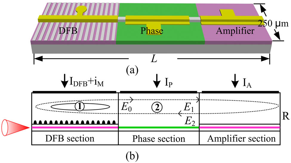
When an additional amplified feedback section is added to the PFL, the feedback strength can be adjusted separately. This is the so-called amplified feedback laser (AFL)[11], which is shown in Fig. 1(a). In the AFL, high-frequency, finely tunable, mode-beating frequencies (i.e. PP resonance peaks) have been measured[13]. In this Letter, we demonstrate the modulated bandwidth enhancement of the AFL with the aid of PP resonance effects. A bandwidth () enhancement from 12 to 27 GHz is numerically and experimentally demonstrated.
Sign up for Chinese Optics Letters TOC. Get the latest issue of Chinese Optics Letters delivered right to you!Sign up now
Figure 1.Schematic diagram of the monolithically integrated AFL. It consists of a DFB section, a phase section, and an amplified section.
Firstly, an AFL composed of a 220 μm DFB section, a 300 μm phase-control section, and a 320 μm amplifier section is fabricated, as shown in Fig. 1. The device structure of the AFL is grown using metal-organic chemical-vapor deposition on n-InP substrates. A gain-coupled Bragg grating has been holographically defined on the upper separately confined heterostructure (SCH) layer of the DFB section. A detailed fabrication process can be found in Refs. [13,14]. The device characterization is performed on a chip level, where two dc needles are used for the current injections into the phase () and amplifier sections (). A ground-signal-ground microwave probe provides a small signal modulation () and DC biasing () for the DFB laser section. Both facets of the device are uncoated, and the laser from the DFB facet is coupled into a tapered single-mode fiber. In the experiment, the working temperature of the device is controlled using a thermoelectric cooler.
Firstly, we investigate the characteristic of the AFL under various dc biasing. The aim is to identify the working conditions under which the PP resonance dominates. The threshold current of the DFB is 24 mA and is fixed at 90 mA. The phase current is fixed at 0 mA and the amplifier current is varied from 0 to 50 mA. The area plots in the first row of Fig. 2 illustrate how the optical spectra are influenced by the amplifier current (). For , the laser works at a stable single-mode emission, as shown in Fig. 2(a1). Through a photo detector, we obtain the corresponding RF spectrum, which only resembles a noise floor. The small-signal modulation responses are depicted in the third column of Fig. 2. As shown in Fig. 2(a3), the modulated bandwidth is just 12 GHz, due to the limitation of the relaxation oscillation frequency. Here, the small-signal response is measured through a vector network analyzer (VNA, HP 8510C). As increases to 20 mA, multi-mode lasing with a mode spacing of 23 GHz is obtained, as shown in Fig. 2(b1). The mode-beating state is confirmed from the RF spectrum as well, where an oscillation frequency of 23 GHz emerges. Fig. 2(b3) shows the corresponding small-signal response. The generation of the PP resonance is accompanied by the enhancement of the bandwidth up to 26 GHz, which coincides well with the simulation analysis. It is verified experimentally that the modulated bandwidth of the AFL can be enhanced using the PP resonance.
Figure 2.Various lasing states of the device for and . varies from top to bottom as (a) 5, (b) 20, and (c) 15 mA. (a1)–(c1) Measured optical spectra. (a2)–(c2) Measured RF power spectra. (a3)–(c3) Measured small-signal responses. Here, the temperature is 22 °C.
However, the results of Fig. 2(b1) and Fig. 2(b3) still cannot fit our requirements. The reasons are twofold: first, the laser works at a multi-mode emission with a side mode suppression ratio (SMSR) of less than 10 dB. Second, the over-shoot in the resonance peak is more than 17 dB. The two facts indicate that the device cannot be well qualified for optical transmitters in a communication system. Nevertheless, adjusting can potentially solve the problem. As shown in Fig. 2(c1), the SMSR will increase to 36 dB when decreases to 15 mA. At the same time, the modulated bandwidth can be enhanced up to 25.2 GHz with an in-band flatness of , as shown in Fig. 2(c3). No frequency tone emerges in the RF spectrum shown in Fig. 2(c2).
Figure 3 shows the relationship between the optical spectra and the small-signal response, the aim of which is to illustrate how the feedback strength influences the PP resonance and modulation response. As shown in Fig. 3(a), the increase of results in the increase of the feedback strength, which then results in the increase of the mode spacing and the enhancement of the PP resonance. The corresponding small signal modulation response is depicted in Fig. 3(b). As can be seen, the increase of the amplified current from 15 to 19 mA is accompanied by an increase of the PP resonance frequency from 20 to 23 GHz. Over-shoots in the resonance peak, which increases from 7 to 17 dB, are measured with the increase of . So, a compromise should be made between the highly modulated response bandwidth and the low over-shoot in the PP resonance peak. By selecting a proper lasing state at which the laser lies in the onset of the mode-beating oscillation, we can obtain a flat, small-signal modulated response, as well as an enhanced modulated bandwidth.
Figure 3.Various lasing states of the device for and . varies from 15 to 19 mA. (a) Optical spectra. (b) Small-signal modulated responses. Here, the temperature is 22 °C.
To further illustrate the mode-beating frequency tuning range and the working range of the modulated bandwidth enhancement, the mode-beating frequency is summarized by a similar contour plot in the plane for . As shown in Fig. 4(a), the oscillations occur periodically with the currents, which result from the change in the feedback phase due to the refractive index change in the feedback cavity. When is fixed, the oscillation frequency decreases with the decrease of the feedback strength as increases. The mode-beating frequency increases with the increased feedback strength as increases[15]. When the two currents are varied simultaneously along a branch marked by the arrow in Fig. 4(a), a continuous oscillation frequency tuning from 11 to 40 GHz can be obtained. An example of the RF power spectra with the beating frequency tuned from 30 to 40 GHz is plotted in Fig. 4(b).
Figure 4.(a) Experimentally measured mapping of the mode-beating frequency in the plane of phase and amplified section currents for . The white areas correspond to the CW output. The different levels of color represent the beating output with different frequencies ranging from 10 to 40 GHz. (b) An example of the RF spectra with beating frequency tuning from 30 to 40 GHz. Here, the bias currents vary along the black row marked in (a).
The dependence of the small-signal modulated response on the temperature is also investigated. Figure 5 shows the small-signal modulated response at 25, 22, 17, and 13 °C. When the temperature decreases, the modulated bandwidth increases from 24 to 27 GHz, with a decreased over-shoot from 12 to 3 dB. An enhanced bandwidth of 27 GHz with an in-band flatness of is experimentally confirmed at 13 °C. The increase of the modulated bandwidth can be derived from the intrinsic increase of the CP resonance frequency. Then, by tuning the PP resonance frequency, a wider modulated bandwidth can be obtained. Therefore, by optimizing the gain materials to increase the CP resonance frequency, and by selecting the proper PP resonance peak, the modulated bandwidth can theoretically be further improved to greater than 40 GHz.
Figure 5.Measured small-signal modulated responses at different temperatures. Here, the DFB and phase currents are fixed at 80 and 0 mA, respectively. The amplified current is adjusted slightly to enable the laser to lie in the states of enhancing the modulated bandwidth. The inset shows that the bandwidth () varies from 24 to 27 GHz.
In order to further demonstrate the tuning range of the PP resonance peak and how the PP resonance influences the modulated bandwidth enhancement in the AFL, theoretical simulations are carried out. Here, we use a commercial package VPItransmissionMakerTM, which can solve the problems that come with using a transmission line laser model[16]. The parameters used in the simulations are set by referring to Ref. [13], and are listed in Table 1.
For a better understanding of the PP resonance in the AFL, one has to know two key parameters: the field feedback strength and the field feedback phase [11]: where is the reflectivity of the amplified section facet and is the mean amplifier gain adjusted by the amplified current (). For an AFL with a fixed device length (, , and ), the parameters and can be easily varied by changing and . is proportional to . Different values of and correspond to various operation states, including single-mode lasing, multimode beating, and chaos[13]. Among these states, mode-beating self-pulsation interests us most for its potential in enhancing the modulated bandwidth by PP resonance effects.
The mapping of the mode-beating areas of the AFL in the plane of phase and the amplified section currents is depicted in Fig. 6(a), where the color scale represents the different beating frequencies. The results agree with the experimental results of Fig. 4(a). Here, a continuous beating frequency from 8 to 35 GHz is obtained. However, the PFL differs from the AFL due to the absence of an amplified section. In order to illustrate the difference of the beating tuning between them, we depict the beating frequency tuning of the PFL in Fig. 6(b), where , , , and the reflectivity of the facet of the phase section is set to 1. As can be seen, the mode-beating ranges of the PFL are limited, and the frequency tuning range is less than 4 GHz, due to the absence of an amplified section.
Figure 6.(a) Mapping of the mode-beating frequency of the AFL in the plane of phase and the amplified section currents when is 80 mA. The white areas correspond to the CW output. The different levels of color represent the beating outputs of different frequencies from 8 to 35 GHz. The five dots represent the different working conditions of the AFL. (b) Beating frequency tuning of the PFL for different when is 80 mA.
Figure 7 shows the simulated small-signal modulated response of the AFL with different values of , where and are fixed at 80 and 29 mA, respectively. The bias currents and working states are marked in Fig. 6 with black dots. For , the AFL works at single-mode lasing and the CP resonance dominates where the bandwidth () is just 12 GHz. However, when the AFL works in the mode-beating regions, the modulated bandwidth will be enhanced due to the PP resonance. For , a 15 GHz PP resonance peak appears with an enhanced bandwidth of 20 GHz. As can be seen, by varying from 0 to 70 mA, the PP resonance peak will increase from 15 to 32 GHz, with an enhanced modulated bandwidth from 20 to 35 GHz. However, for , the response curve is not flat; i.e., the gap between the CP resonance and PP resonance is not fully filled. Therefore, the PP resonance peak should be carefully adjusted to fill the gap between the CP and PP resonance peaks, which can be easily settled by selecting a proper . Thus, when the device length is fixed, we can obtain a flat response curve by adjusting the bias currents.
Figure 7.Simulated small-signal modulated response of the AFL with different . Here, and are fixed at 80 and 29 mA, respectively. The different working conditions are marked in Fig. 2 with black dots.
For different feedback cavity lengths, we also calculate and plot the normalized small-signal response of the AFL. As shown in Fig. 8, where the DFB and amplified lengths are fixed at 220 and 320 μm, the phase section varies from 340 to 800 μm. Here, and are fixed at 80 and 29 mA, respectively, while is adjusted to make the bandwidth () as high as possible. We also make sure that the gap between the CP and PP resonances is fully filled. As can be seen, the flat response curves can be obtained by adjusting for all of the feedback lengths. The modulated bandwidth enhancement is determined not only by the bias currents, but also by the feedback length. And, it is easier to obtain a higher modulated bandwidth by shortening the cavity length.
Figure 8.Normalized small-signal response of the AFL with different feedback lengths. Here, and are fixed at 220 and 320 μm, and is varied from 340 to 800 μm. and are fixed at 80 and 29 mA, respectively, while is adjusted to make the bandwidth () as high as possible. is 25, 50, and 67 mA. We also make sure that the gap between the CP and PP resonances is fully filled.
In conclusion, modulated bandwidth enhancement in an AFL is demonstrated both experimentally and numerically. An enhanced bandwidth of 27 GHz with an in-band flatness of is experimentally confirmed at 13 °C. It is numerically confirmed that the modulated bandwidth of the AFL can be enhanced to 2 times its original CP-determined bandwidth, with more controlled flexibility of the flatness of the small-signal response.
Liqiang Yu, Lu Guo, Dan Lu, Chen Ji, Hao Wang, Lingjuan Zhao. Modulated bandwidth enhancement in an amplified feedback laser[J]. Chinese Optics Letters, 2015, 13(5): 051401