
Peining Wang, Penghui Yang, Gangwen Liu, Zhenghe Bai, Weimin Li. Design and simulation of beam injection scheme for diffraction limited storage ring[J]. High Power Laser and Particle Beams, 2023, 35(12): 124006
- High Power Laser and Particle Beams
- Vol. 35, Issue 12, 124006 (2023)
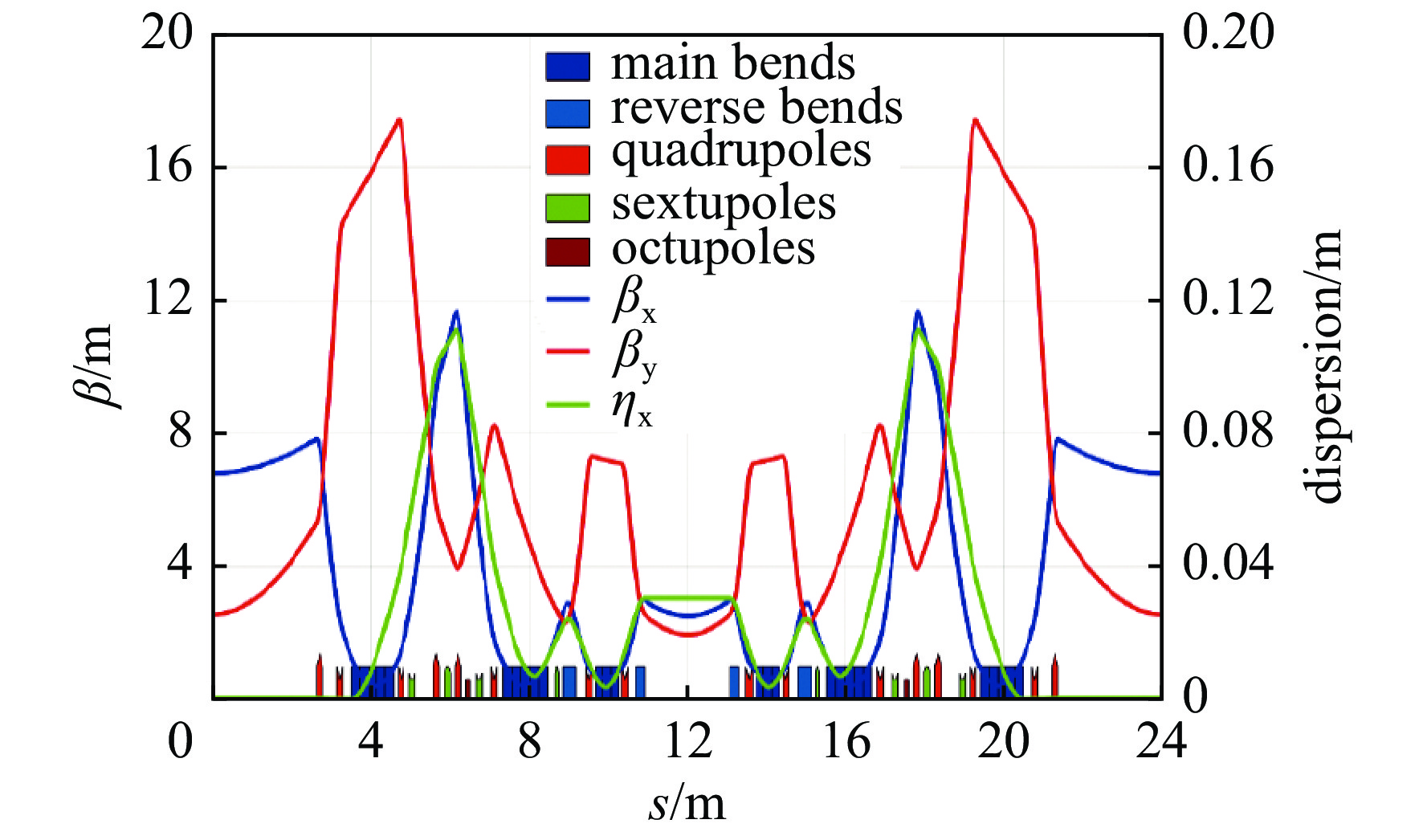
Fig. 1. Magnet layout and linear optical parameters of one period HALF lattice

Fig. 2. Dynamic aperture of the HALF storage ring
Fig. 3. Schematic layout of injection devices for the bump injection scheme with anti-septum (K2)
Fig. 4. Element layout of anti-septum injection scheme
Fig. 5. Position of the first six turns of injection beam
Fig. 6. Injection efficiency of anti-septum injection scheme
Fig. 7. Influence of anti-septum injection on the stored beam
Fig. 8. Schematic layout of injection devices for the multipole kicker injection scheme
Fig. 9. Field distribution of nonlinear kicker
Fig. 10. First turn trajectory of the injection particle and specific parameters of the injection scheme
Fig. 11. Accumulation process after pulsed multipole injection
Fig. 12. Injection efficiency of pulsed multipole injection with error
Fig. 13. Influence of pulsed multipole injection on the stored beam
Fig. 14. Schematic layout of injection devices for the longitudinal injection scheme
Fig. 15. Upper and lower boundaries of longitudinal phase space in longitudinal injection
Fig. 16. δ 0 and δ s change with high frequency cavity voltage
Fig. 17. Accumulation process of injection beam in longitudinal injection
|
Table 1. Main parameters of the HALF storage ring
|
Table 2. Main parameters of pulsed multipole injection scheme
|
Table 3. Main parameters of longitudinal injection scheme

Set citation alerts for the article
Please enter your email address
© Copyright 2018-2021 | Chinese Laser Press. All Rights Reserved 沪ICP备15018463号-20