• Photonics Research
  • Vol. 8, Issue 3, 235 (2020)
Lingjie Yu1, Chenzhi Yuan1、2, Renduo Qi1, Yidong Huang1、3、4, and Wei Zhang1、3、4、*
Author Affiliations
  • 1Beijing National Research Center for Information Science and Technology (BNRist), Beijing Innovation Center for Future Chips, Electronic Engineering Department, Tsinghua University, Beijing 100084, China
  • 2Institute of Fundamental and Frontier Sciences, University of Electronic Science and Technology of China, Chengdu 610054, China
  • 3Frontier Science Center for Quantum Information, Beijing 100084, China
  • 4Beijing Academy of Quantum Information Sciences, Beijing 100193, China
  • show less
    DOI: 10.1364/PRJ.376805 Cite this Article Set citation alerts
    Lingjie Yu, Chenzhi Yuan, Renduo Qi, Yidong Huang, Wei Zhang. Hybrid waveguide scheme for silicon-based quantum photonic circuits with quantum light sources[J]. Photonics Research, 2020, 8(3): 235 Copy Citation Text show less
    Typical structures of (a) a strip waveguide and (b) a shallow-ridge waveguide, with waveguide parameters close to the fabricated samples in the experiment; (c) the calculated dispersions of the two waveguides in the telecom band. The strip waveguide has small anomalous dispersion, while the shallow-ridge waveguide has large normal dispersion.
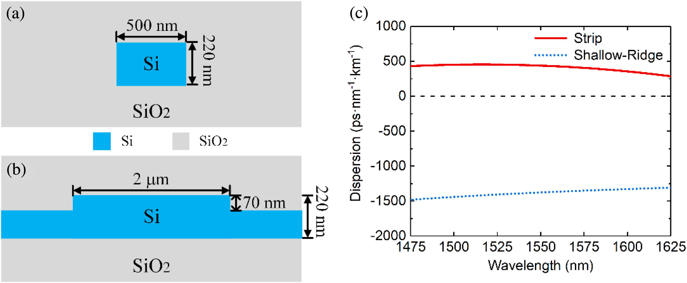
    Fig. 1. Typical structures of (a) a strip waveguide and (b) a shallow-ridge waveguide, with waveguide parameters close to the fabricated samples in the experiment; (c) the calculated dispersions of the two waveguides in the telecom band. The strip waveguide has small anomalous dispersion, while the shallow-ridge waveguide has large normal dispersion.
    Calculated (a) phase mismatch and (b) biphoton spectra of degenerate SFWM processes in the strip waveguide and the shallow-ridge waveguides; the calculated (c) phase mismatch and (d) biphoton spectra of non-degenerate SFWM processes in the strip waveguide and the shallow-ridge waveguides. The length of the strip waveguide is 5 mm, while three shallow-ridge waveguide lengths are considered, which are 3 mm, 8 mm, and 15 mm, respectively.
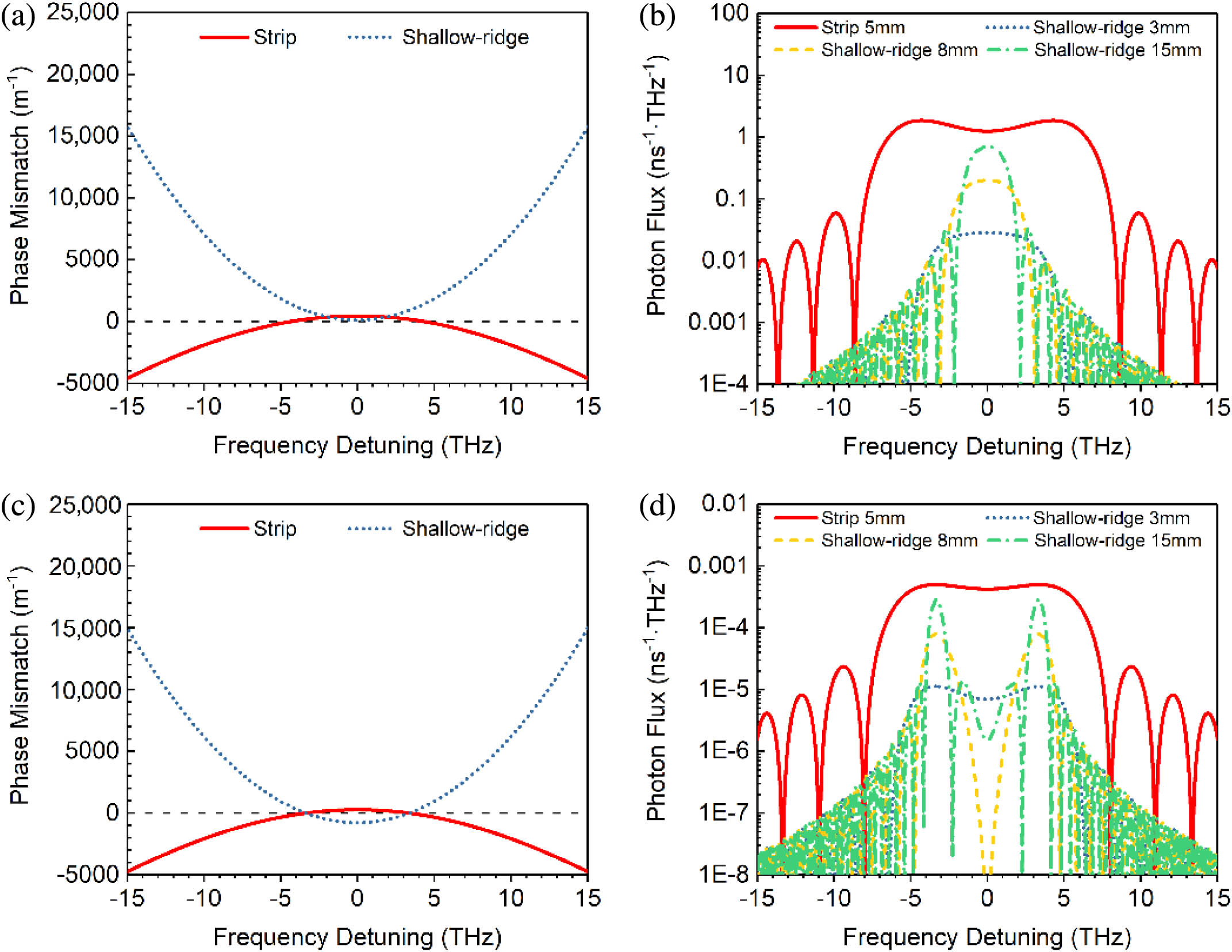
    Fig. 2. Calculated (a) phase mismatch and (b) biphoton spectra of degenerate SFWM processes in the strip waveguide and the shallow-ridge waveguides; the calculated (c) phase mismatch and (d) biphoton spectra of non-degenerate SFWM processes in the strip waveguide and the shallow-ridge waveguides. The length of the strip waveguide is 5 mm, while three shallow-ridge waveguide lengths are considered, which are 3 mm, 8 mm, and 15 mm, respectively.
    Waveguide samples and their typical measured transmission spectra. (a) The sketch of the transition section in the hybrid waveguide sample with parameters indicated and (b) an SEM picture of a part of the section; (c) the sketches of the hybrid and shallow-ridge waveguides on the chip; typical measured transmission spectra of (d) 8 mm waveguide samples and (e) 17 mm waveguide samples.
    Fig. 3. Waveguide samples and their typical measured transmission spectra. (a) The sketch of the transition section in the hybrid waveguide sample with parameters indicated and (b) an SEM picture of a part of the section; (c) the sketches of the hybrid and shallow-ridge waveguides on the chip; typical measured transmission spectra of (d) 8 mm waveguide samples and (e) 17 mm waveguide samples.
    Experiment setup for photon pair generation by non-degenerate SFWM. CW Laser 1/2, two tunable CW lasers for pump light generation; CWDM 1/2, optical filters made of coarse wavelength division multiplexing devices; C, com; T, transmission; R, reflection; FPC, fiber polarization controller; DWDM, optical filter made of dense wavelength-division multiplexing devices; SPD, single-photon detector; TCSPC, time-correlated single-photon counting circuit.
    Fig. 4. Experiment setup for photon pair generation by non-degenerate SFWM. CW Laser 1/2, two tunable CW lasers for pump light generation; CWDM 1/2, optical filters made of coarse wavelength division multiplexing devices; C, com; T, transmission; R, reflection; FPC, fiber polarization controller; DWDM, optical filter made of dense wavelength-division multiplexing devices; SPD, single-photon detector; TCSPC, time-correlated single-photon counting circuit.
    Experimental results of photon pair generation in the waveguide samples. Typical results of the coincidence measurement of 8 mm (a) hybrid and (b) shallow-ridge waveguides; coincidence-to-accidental ratio (CAR) comparison of (c) 8 mm and (d) 17 mm waveguide samples under different signal/idler wavelengths; (e) calculated SFWM photon flux spectra of the 3 mm strip waveguide in the 8 mm hybrid waveguide sample and 8 mm shallow-ridge waveguide sample under the pump conditions used in the experiment; (f) calculated SFWM photon flux spectra of the 3 mm strip waveguide in the 17 mm hybrid waveguide sample and 17 mm shallow-ridge waveguide sample under the pump conditions used in the experiment. The orange arrows indicate the pump wavelengths, while the blue arrows indicate the center wavelengths of the signal/idler filters used in the experiment. In (c), (d), (e), and (f), the bottom x axis indicates the wavelength, while the top x axis indicates the corresponding frequency detuning relative to 1554.5 nm, which is the average wavelength of two pump lights.
    Fig. 5. Experimental results of photon pair generation in the waveguide samples. Typical results of the coincidence measurement of 8 mm (a) hybrid and (b) shallow-ridge waveguides; coincidence-to-accidental ratio (CAR) comparison of (c) 8 mm and (d) 17 mm waveguide samples under different signal/idler wavelengths; (e) calculated SFWM photon flux spectra of the 3 mm strip waveguide in the 8 mm hybrid waveguide sample and 8 mm shallow-ridge waveguide sample under the pump conditions used in the experiment; (f) calculated SFWM photon flux spectra of the 3 mm strip waveguide in the 17 mm hybrid waveguide sample and 17 mm shallow-ridge waveguide sample under the pump conditions used in the experiment. The orange arrows indicate the pump wavelengths, while the blue arrows indicate the center wavelengths of the signal/idler filters used in the experiment. In (c), (d), (e), and (f), the bottom x axis indicates the wavelength, while the top x axis indicates the corresponding frequency detuning relative to 1554.5 nm, which is the average wavelength of two pump lights.
    (a) Sketch of the circuit for time-bin entanglement generation and its measurement setup. The gray rectangle with a black frame represents the chip. The blue line indicates the shallow-ridge waveguide, which realizes the UMZI and the grating couplers. The red line indicates the strip waveguide, which is used as the nonlinear medium for degenerate SFWM. By placing the optical filter system before the SPDs, the post-selected photon pairs are mainly generated in the strip waveguide and the impact of SFWM in the UMZI can be avoided. (b) The calculated biphoton spectra of the degenerate SFWM in the strip waveguide and the shallow-ridge waveguide in the circuit; (c) the calculated biphoton spectra of the degenerate SFWM in different parts if the UMZI is also realized by the strip waveguide.
    Fig. 6. (a) Sketch of the circuit for time-bin entanglement generation and its measurement setup. The gray rectangle with a black frame represents the chip. The blue line indicates the shallow-ridge waveguide, which realizes the UMZI and the grating couplers. The red line indicates the strip waveguide, which is used as the nonlinear medium for degenerate SFWM. By placing the optical filter system before the SPDs, the post-selected photon pairs are mainly generated in the strip waveguide and the impact of SFWM in the UMZI can be avoided. (b) The calculated biphoton spectra of the degenerate SFWM in the strip waveguide and the shallow-ridge waveguide in the circuit; (c) the calculated biphoton spectra of the degenerate SFWM in different parts if the UMZI is also realized by the strip waveguide.
    (a) Sketch of the circuit for path entanglement generation, distribution, and analysis with its measurement setup. The gray rectangle with a black frame represents the chip. The two black dashed lines divide the chip into three parts: the quantum light sources, the quantum state distribution, and the quantum state analyzer. The red lines indicate the 5 mm strip waveguides for photon pair generation by non-degenerate SFWM. The blue lines indicate the shallow-ridge waveguides. The phase shifters are shown in orange. By placing the optical filter system before the SPDs, the frequency-degenerate photon pairs are selected and the impact of non-degenerate SFWM in the quantum state distribution and state analyzer sections can be avoided. (b) The calculation results of the biphoton spectra of different sections, including the strip waveguides in quantum light sources, the four waveguides for quantum state distribution, and the waveguides in the MZIs in the quantum state analyzer; (c) the calculation results if all the waveguides in the calculation are strip waveguides.
    Fig. 7. (a) Sketch of the circuit for path entanglement generation, distribution, and analysis with its measurement setup. The gray rectangle with a black frame represents the chip. The two black dashed lines divide the chip into three parts: the quantum light sources, the quantum state distribution, and the quantum state analyzer. The red lines indicate the 5 mm strip waveguides for photon pair generation by non-degenerate SFWM. The blue lines indicate the shallow-ridge waveguides. The phase shifters are shown in orange. By placing the optical filter system before the SPDs, the frequency-degenerate photon pairs are selected and the impact of non-degenerate SFWM in the quantum state distribution and state analyzer sections can be avoided. (b) The calculation results of the biphoton spectra of different sections, including the strip waveguides in quantum light sources, the four waveguides for quantum state distribution, and the waveguides in the MZIs in the quantum state analyzer; (c) the calculation results if all the waveguides in the calculation are strip waveguides.
    Filter Group NumberITU ChannelCenter Wavelength/nmLoss/dB3 dB Bandwidth/nmITU ChannelCenter Wavelength/nmLoss/dB3 dB Bandwidth/nm
    1C301553.32.90.47C271555.72.40.59
    2C331550.93.10.43C241558.21.90.45
    3C351549.32.70.50C221559.82.90.47
    4C461540.63.30.52C111568.82.00.51
    Table 1. Optical Filters for Signal/Idler Photons
    Lingjie Yu, Chenzhi Yuan, Renduo Qi, Yidong Huang, Wei Zhang. Hybrid waveguide scheme for silicon-based quantum photonic circuits with quantum light sources[J]. Photonics Research, 2020, 8(3): 235
    Download Citation