
Efim Khazanov, Andrey Shaykin, Igor Kostyukov, Vladislav Ginzburg, Ivan Mukhin, Ivan Yakovlev, Alexander Soloviev, Ivan Kuznetsov, Sergey Mironov, Artem Korzhimanov, Denis Bulanov, Ilya Shaikin, Anton Kochetkov, Alexey Kuzmin, Mikhail Martyanov, Vladimir Lozhkarev, Mikhail Starodubtsev, Alexander Litvak, Alexander Sergeev. eXawatt Center for Extreme Light Studies[J]. High Power Laser Science and Engineering, 2023, 11(6): 06000e78
- High Power Laser Science and Engineering
- Vol. 11, Issue 6, 06000e78 (2023)
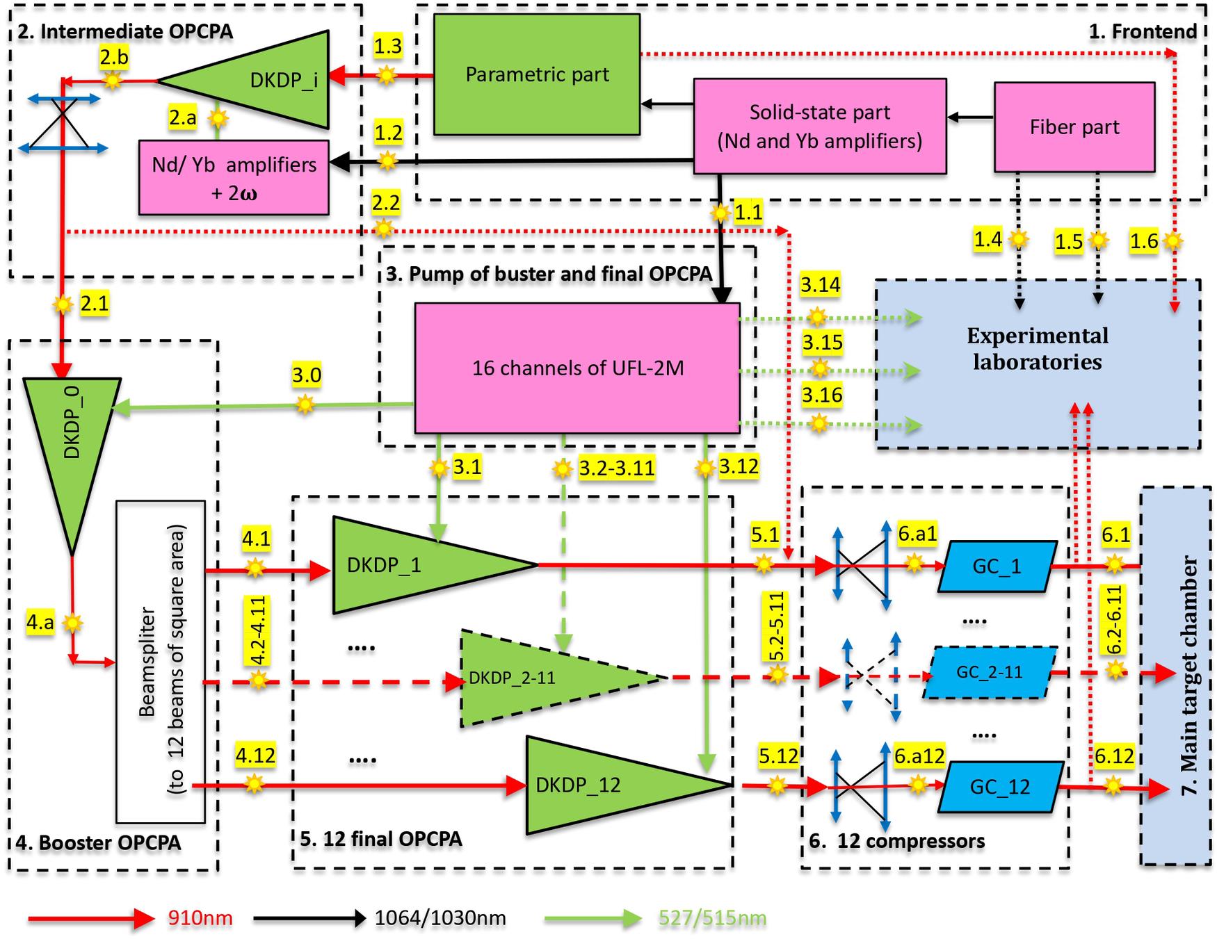
Fig. 1. General block diagram of the XCELS laser. DKDP_i, nonlinear crystal in intermediate OPCPA; DKDP_0, nonlinear crystal in booster OPCPA; DKDP_1–12, nonlinear crystals in final OPCPAs; GC, grating compressor.
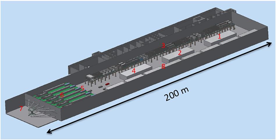
Fig. 2. General view of the building for the XCELS project: frontend (1); intermediate OPCPA (2); pumping zone for wide-aperture OPCPAs (3); booster OPCPA (4); final OPCPAs (5); transport telescopes and optical compressors (6); main target chamber (7); experimental laboratories (8).
Fig. 3. Schematic diagram of the frontend. MO, master oscillator; NF, nonlinear fiber; FA, fiber amplifier; FRA, fiber regenerative amplifier; FSRA, femtosecond regenerative amplifier; DRA, disk regenerative amplifier; DMA, disk multipass amplifier; NA, neodymium amplifier; YA, ytterbium amplifier; WLG, white light generator; FOPA, parametric amplifier; XPW, orthogonal polarization generator; GS, stretcher on diffraction grating; AOPDF, acousto-optical programmable dispersion filter.
Fig. 4. Measured pulse intensity and phase at the output of a parametric amplifier based on a BBO crystal[46].
Fig. 5. Variants of the optical scheme of the intermediate OPCPA when pumped by a lamp-pumped neodymium glass rod laser (a), a lamp-pumped neodymium glass active-mirror laser (b), (c) and two diode-pumped Yb:YAG cryogenic disk lasers (d), (e) (see also Table 3 ).
Fig. 6. Signal spectra at the input (black curves) and at the output (red curves) of OPCPA and the shape of the pump pulse (green curves) for the five options shown in Figure 5 and Table 3 . The insets show the dependence of the energy W on the thickness L of the DKDP crystal. The dashed curves in (b) , (d) and (e) show the corresponding dependence for the first OPCPA cascade.
Fig. 7. Optical layout of one channel of the UFL-2M setup[70].
Fig. 8. Booster OPCPA. ARE, auxiliary removable equipment (filters, diaphragms, screens); TM, a mirror on the translator; RM, a rotating mirror, used for alignment and phasing of channels (see Sections 2.8 and 2.9). In the lower left corner there is a diagram of the beam division into 12 replicas (the green square is the pump beam cross-section, the red circle is the signal beam cross-section); one telescope out of twelve is shown.
Fig. 9. Signal spectra at the input (black curve) and output (red curve) of OPCPA and the pump pulse shape (green curve) for booster OPCPA. The inset shows the dependence of the energy W on the thickness L of the DKDP crystal.
Fig. 10. Signal spectra at the input (black curve) and output (red curve) of OPCPA and the pump pulse shape (green curve) for the final OPCPA. The inset shows the dependence of the energy W on the thickness L of the DKDP crystal.
Fig. 11. Expanding telescope and chirped pulse compressor (sizes of beam and gratings G1–G4 are shown to scale), as well as a 17-fs Fourier-transform-limited output pulse.
Fig. 12. Focusing geometry in the main target chamber. For clarity, the parabolic mirror of beam No. 6 is shown transparent, and the input beams are shown for only two channels: the beam input of channel No. 1 coincides with the output of channel No. 7, and vice versa.
Fig. 13. Dependence of the maximum intensity achieved in the focal region on the number of focused beams for ideal phasing (σ = 0) and for different values of the standard deviation σ of the phase mismatch between the beams.
Fig. 14. Scheme of spatial and temporal overlapping of beams at the main focus. TM, mirror on the translator; RM, rotating mirror; DM, deformable mirror; PM, parabolic mirror; WFS, wavefront sensor; QP, quadrature photodiode; FI, focus image; FPM, fiber-optic phase modulator; PD, photodiode; DU, diagnostic unit; RDU, retro-diagnostic unit; MO, microscope objective.
Fig. 15. Illustration of blade alignment.
Fig. 16. Overlapping of counterpropagating channels.
Fig. 17. Adjacent channels overlapping.
Fig. 18. Schemes of post-compression (a), post-compression with spectral filtering (b) and frequency doubling with post-compression (c). NE, nonlinear element; CM, chirped mirror; R( ) is a mirror whose reflection coefficient has a dip in the center of the spectral band; the dichroic mirrors shown in blue reflect the second harmonic of the pulse and transmit the first harmonic.
) is a mirror whose reflection coefficient has a dip in the center of the spectral band; the dichroic mirrors shown in blue reflect the second harmonic of the pulse and transmit the first harmonic. Fig. 19. Spectra (a) and pulse intensity in linear (b) and logarithmic (c) scales at the grating compressor output (red curves), after post-compression (green curves) (see Figure 18(a) ) and after post-compression with spectral filtering (blue curves) (see Figure 18(b) ).
Fig. 20. Pulses of the fundamental harmonic (red curves), the second harmonic (blue curves) and the second harmonic after post-compression (green curves).
Fig. 21. The number of laser pulses that are needed in the experimental schemes proposed in Refs. [118–156]. The blue color shows the minimum required number of laser pulses, while the cyan color shows the maximum number of pulses.
|
Table 1. Characteristics of the XCELS laser and other 100-PW laser projects.
| ||||||||||||||||||||||||||||||||||||||||||||||||||||||||||||||||||||||||||||||||||||||||||||||||||||||||||||||||||||||||||||||||||||||||||||||||||||||||||||||||||||||||||||||||||||||||||||||||||||||||||||||||||||||||||||||
Table 2. Main parameters at key points of the XCELS laser.
| ||||||||||||||||||||||||||||||||||||||||||||||||||||||||||||||||||||||||||||||||||||||||||||||||||||||||||||||||||
Table 3. Five options of intermediate OPCPA (optical schemes are shown in Figures 5(a) –5(e) ).
|
Table 4. Booster OPCPA parameters. All apertures and energies (except for the total pump energy) refer to the homogeneous region of the beam; total aperture is approximately 20% larger.
|
Table 5. Final OPCPA parameters for two options. All apertures and energies (except for the total pump energy) refer to the homogeneous region of the beam; the full aperture is about 20% larger.
|
Table 6. Parameters for two compressor options.
|
Table 7. XCELS laser power and intensity.

Set citation alerts for the article
Please enter your email address
© Copyright 2018-2021 | Chinese Laser Press. All Rights Reserved 沪ICP备15018463号-20