• Chinese Optics Letters
  • Vol. 20, Issue 11, 112601 (2022)
Shichao Yang1、2, Hanlin Huang1、2, Gaoxu Wu1、2, Yanxue Wu1、2, Tian Yang1、2, and Fei Liu1、2、*
Author Affiliations
  • 1State Key Laboratory of Mechanical Transmission, Chongqing University, Chongqing 400044, China
  • 2College of Mechanical Engineering, Chongqing University, Chongqing 400044, China
  • show less
    DOI: 10.3788/COL202220.112601 Cite this Article Set citation alerts
    Shichao Yang, Hanlin Huang, Gaoxu Wu, Yanxue Wu, Tian Yang, Fei Liu. High-speed three-dimensional shape measurement with inner shifting-phase fringe projection profilometry[J]. Chinese Optics Letters, 2022, 20(11): 112601 Copy Citation Text show less
    Three projected patterns. (a)–(c) Three projected fringe patterns. (d)–(f) One section of the three patterns.
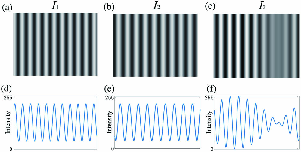
    Fig. 1. Three projected patterns. (a)–(c) Three projected fringe patterns. (d)–(f) One section of the three patterns.
    Detail of finding k.
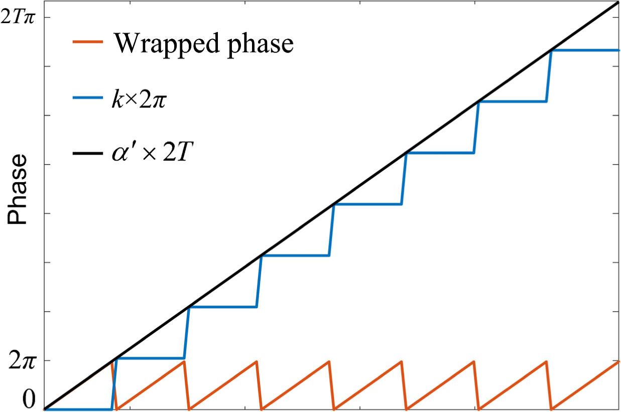
    Fig. 2. Detail of finding k.
    Procedure of the method. (a) One projected pattern. (b) The wrapped phase. (c) Map of A. (d) The shifting phase. (e) The absolute phase. (f) The 3D reconstruction result.
    Fig. 3. Procedure of the method. (a) One projected pattern. (b) The wrapped phase. (c) Map of A. (d) The shifting phase. (e) The absolute phase. (f) The 3D reconstruction result.
    Measurement system.
    Fig. 4. Measurement system.
    Two ceramic spheres. (a) One of the three captured patterns. (b) Wrapped phase map. (c) The 3D reconstruction result of two ceramic spheres.
    Fig. 5. Two ceramic spheres. (a) One of the three captured patterns. (b) Wrapped phase map. (c) The 3D reconstruction result of two ceramic spheres.
    Schematic diagram of measuring distance between sphere centers (L) and diameter of reconstruction results.
    Fig. 6. Schematic diagram of measuring distance between sphere centers (L) and diameter of reconstruction results.
    Six different angles.
    Fig. 7. Six different angles.
    One cartoon mask. (a) One of the three captured patterns. (b) Wrapped phase map of the cartoon mask. (c) The 3D reconstruction result of the cartoon mask. (d) One cross section of the wrapped phase and its counterpart of the reference phase in (a).
    Fig. 8. One cartoon mask. (a) One of the three captured patterns. (b) Wrapped phase map of the cartoon mask. (c) The 3D reconstruction result of the cartoon mask. (d) One cross section of the wrapped phase and its counterpart of the reference phase in (a).
    Two isolated sculptures. (a) One of the three captured patterns. (b) Wrapped phase map of two isolated sculptures. (c) The 3D reconstruction result of two isolated sculptures. (d) One cross section of the wrapped phase and its counterpart of the reference phase in (a).
    Fig. 9. Two isolated sculptures. (a) One of the three captured patterns. (b) Wrapped phase map of two isolated sculptures. (c) The 3D reconstruction result of two isolated sculptures. (d) One cross section of the wrapped phase and its counterpart of the reference phase in (a).
    One colorful sculpture. (a) One of the three captured patterns. (b) Wrapped phase map of the colorful sculpture. (c) One cross section of the wrapped phase and its counterpart of the reference phase in (a). (d) The 3D reconstruction result of the colorful sculpture. (e) Colorful 3D reconstruction result.
    Fig. 10. One colorful sculpture. (a) One of the three captured patterns. (b) Wrapped phase map of the colorful sculpture. (c) One cross section of the wrapped phase and its counterpart of the reference phase in (a). (d) The 3D reconstruction result of the colorful sculpture. (e) Colorful 3D reconstruction result.
    Principle of getting full frame rate.
    Fig. 11. Principle of getting full frame rate.
    Paper airplane with wings vibrating in the wind.
    Fig. 12. Paper airplane with wings vibrating in the wind.
    Vibration track of the airplane.
    Fig. 13. Vibration track of the airplane.
    Moving hand. (a)–(d) show 2D captured patterns in the left and corresponding 3D reconstruction results in the right at the point frame 44, frame 485, frame 1167, and frame 1685.
    Fig. 14. Moving hand. (a)–(d) show 2D captured patterns in the left and corresponding 3D reconstruction results in the right at the point frame 44, frame 485, frame 1167, and frame 1685.
    Table 1. Comparisons of the Two Methods
    Shichao Yang, Hanlin Huang, Gaoxu Wu, Yanxue Wu, Tian Yang, Fei Liu. High-speed three-dimensional shape measurement with inner shifting-phase fringe projection profilometry[J]. Chinese Optics Letters, 2022, 20(11): 112601
    Download Citation