
Huan Pengcheng, Wang Xiaonan, Zhu Tiancai, Chen Wengang, Hu Zengrong, Zhang Min, Chen Changjun. Microstructure and Mechanical Properties of Laser Welded Joint of 800 MPa Grade Hot-Rolled High Strength Steel[J]. Chinese Journal of Lasers, 2019, 46(1): 102002
- Chinese Journal of Lasers
- Vol. 46, Issue 1, 102002 (2019)
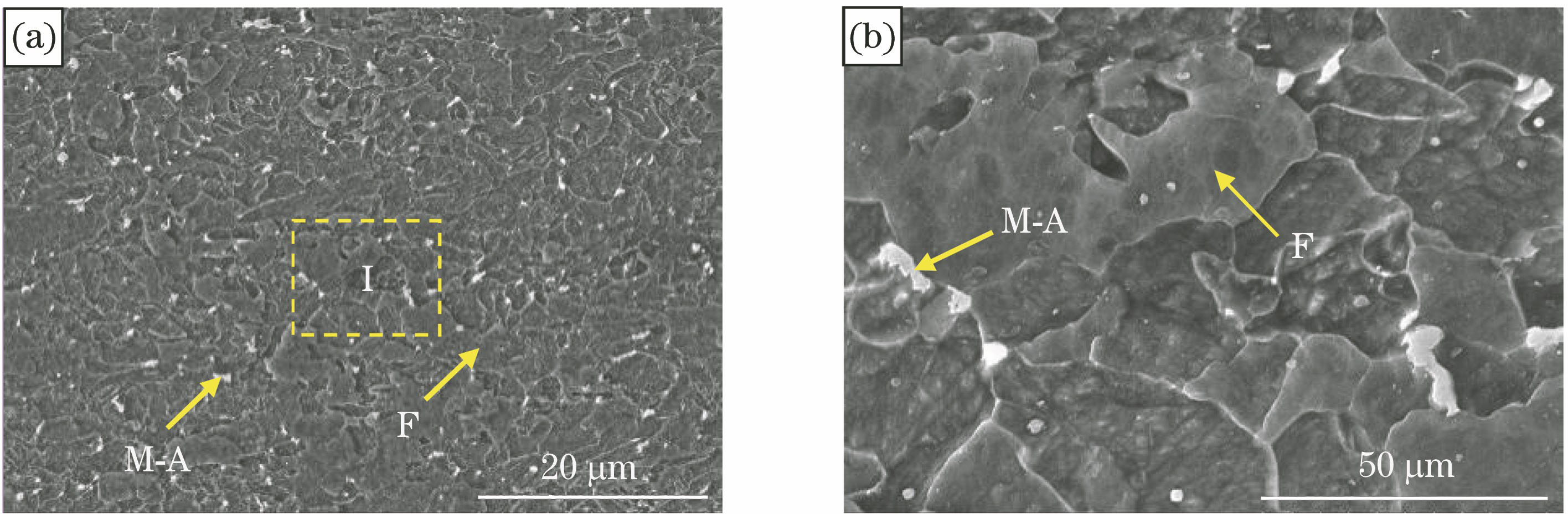
Fig. 1. Microstructure of experimental steel. (a) SEM morphology with low magnification; (b) enlarged microstructure of I area
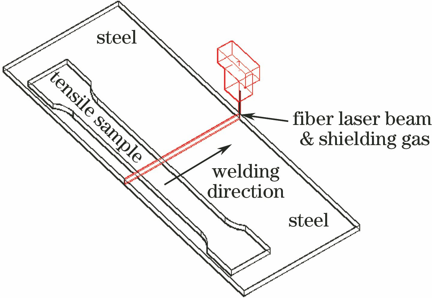
Fig. 2. Schematic of tailored blank laser welding
Fig. 3. Size of tensile sample
Fig. 4. Size of impact sample
Fig. 5. Macro morphology of welded joints obtained at different heat inputs. (a) 30.0 J/mm; (b) 42.0 J/mm; (c) 48.0 J/mm; (d) 54.0 J/mm
Fig. 6. Microstructures of welded joint obtained at heat input of 42.0 J/mm. (a) Low magnification of WS; (b) high magnification of WS; (c) CGHAZ; (d) FGHAZ
Fig. 7. Microstructure of MGHAZ of welded joint obtained at heat input of 42.0 J/mm. (a) Near MGHAZ; (b) enlarged image of II area
Fig. 8. Microhardness distributions of full-penetration weld joints obtained at different heat inputs. (a) 42.0 J/mm; (b) 48.0 J/mm; (c) 54.0 J/mm
Fig. 9. (a) Images of tensile samples of welded joint after fracture; (b) engineering stress-engineering strain curves of tensile samples
Fig. 10. SEM images of tensile fracture of full-penetration weld joints obtained at different heat inputs and base metal
Fig. 11. Impact fracture morphology of weld seam obtained at different heat input and base metal
Fig. 12. Impact fracture morphology of weld seam obtained at different heat inputs and base metal. (a) 30.0 J/mm; (b) enlarged image of III area; (c) 42.0 J/mm;(d) 48.0 J/mm; (e) 54.0 J/mm; (f) base metal
|
Table 1. Chemical composition of experimental steel
|
Table 2. Mechanical properties of experimental steel
|
Table 3. Welding parameters of experimental steel
|
Table 4. Tensile properties of welded joints
|
Table 5. Impact energy and fracture position of weld seam obtained at different heat inputs

Set citation alerts for the article
Please enter your email address
© Copyright 2018-2021 | Chinese Laser Press. All Rights Reserved 沪ICP备15018463号-20