• Chinese Optics Letters
  • Vol. 13, Issue 2, 020501 (2015)
Yuegang Chen1、2 and Zhiyuan Li2、*
Author Affiliations
  • 1Department of Physics, Guizhou University, Guiyang 550025, China
  • 2Laboratory of Optical Physics, Institute of Physics, Chinese Academy of Science, Beijing 100190, China
  • show less
    DOI: 10.3788/COL201513.020501 Cite this Article Set citation alerts
    Yuegang Chen, Zhiyuan Li. Free space optical beam coupled to surface plasmonic polariton waves via designed grooves in metal film[J]. Chinese Optics Letters, 2015, 13(2): 020501 Copy Citation Text show less
    Schematic of the surface electromagnetic wave hologram. (a) The writing process, where metal surface is an x−y plane, (b) The reading process.
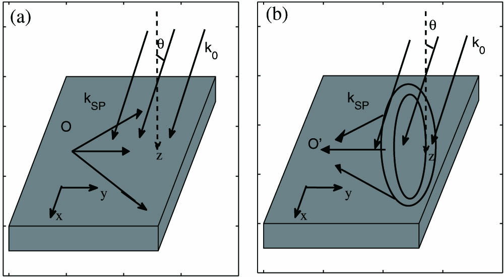
    Fig. 1. Schematic of the surface electromagnetic wave hologram. (a) The writing process, where metal surface is an xy plane, (b) The reading process.
    Design of the groove pattern used to couple a plane wave in free space to a focusing SPP wave on a metal surface. Panels (a)–(d), (e)–(h), and (i)–(l) are for the incident angles θ=0°, θ=15°, and θ=30°, respectively. Panels (a), (e), and (i) show the interference intensity pattern, while (b), (f), and (j) show the groove pattern. (c), (g), (k), and (d), (h), (l) display the reconstruction result of the intensity distribution in the x−y plane and x−z plane where y=−8 μm, respectively.
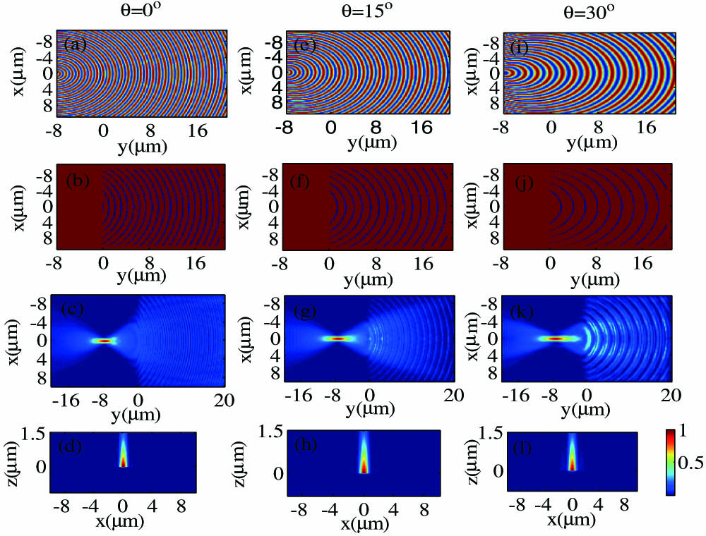
    Fig. 2. Design of the groove pattern used to couple a plane wave in free space to a focusing SPP wave on a metal surface. Panels (a)–(d), (e)–(h), and (i)–(l) are for the incident angles θ=0°, θ=15°, and θ=30°, respectively. Panels (a), (e), and (i) show the interference intensity pattern, while (b), (f), and (j) show the groove pattern. (c), (g), (k), and (d), (h), (l) display the reconstruction result of the intensity distribution in the xy plane and xz plane where y=8μm, respectively.
    Influence of groove depth and incident angle on the coupling efficiencies. (a) Groove depth h. (b) Incident angle θ.
    Fig. 3. Influence of groove depth and incident angle on the coupling efficiencies. (a) Groove depth h. (b) Incident angle θ.
    Design of the groove pattern used to couple a plane wave to dual-points SPPs on a metal surface. For θ=0°, (a) is the interference intensity pattern and (b) is the groove pattern. For reconstruction intensity, (c) is the x−y plane and (d) is x−z plane when y=−8 μm. For θ=15°, (e) is the interference intensity pattern and (f) is the groove pattern. For the reconstruction intensity, (g) is the x−y plane and (h) is the x−z plane when y=−8 μm. (i) The influence of the groove depth on the coupling efficiency for θ=0° and θ=15°.
    Fig. 4. Design of the groove pattern used to couple a plane wave to dual-points SPPs on a metal surface. For θ=0°, (a) is the interference intensity pattern and (b) is the groove pattern. For reconstruction intensity, (c) is the xy plane and (d) is xz plane when y=8μm. For θ=15°, (e) is the interference intensity pattern and (f) is the groove pattern. For the reconstruction intensity, (g) is the xy plane and (h) is the xz plane when y=8μm. (i) The influence of the groove depth on the coupling efficiency for θ=0° and θ=15°.
    Yuegang Chen, Zhiyuan Li. Free space optical beam coupled to surface plasmonic polariton waves via designed grooves in metal film[J]. Chinese Optics Letters, 2015, 13(2): 020501
    Download Citation