1Key Laboratory for Quantum Optics, Shanghai Institute of Optics and Fine Mechanics, Chinese Academy of Sciences, Shanghai 201800, China
2Caltech Optical Imaging Laboratory, Andrew and Peggy Cherng Department of Medical Engineering, Department of Electrical Engineering, California Institute of Technology, Pasadena, California 91125, USA
The optical memory effect is an interesting phenomenon that has attracted considerable attention in recent decades. Here, we present a new physical picture of the optical memory effect, in which the memory effect and the conventional spatial shift invariance are united. Based on this picture we depict the role of thickness, scattering times, and anisotropy factor and derive equations to calculate the ranges of the angular memory effect (AME) of different scattering components (ballistic light, singly scattered, doubly scattered, etc.), and hence a more accurate equation for the real AME ranges of volumetric turbid media. A conventional random phase mask model is modified according to the new picture. The self-consistency of the simulation model and its agreement with the experiment demonstrate the rationality of the model and the physical picture, which provide powerful tools for more sophisticated studies of the memory-effect-related phenomena and wavefront-sensitive techniques, such as wavefront shaping, optical phase conjugation, and optical trapping in/through scattering media.
1. INTRODUCTION
In 1988 Feng et al. derived and proposed the angular memory effect (AME), also called the tilt memory effect in a waveguide geometry [1], and later observed the shift-invariant laser speckle through a ground glass disk [2]. In their theory, the AME range is inversely proportional to the thickness of the medium without a consideration of optical parameters of scattering media, such as scattering coefficient and anisotropy factor. They also pointed out that the presence of the memory effect in the multiple-scattering situation is less apparent intuitively, but did not give further explanation. Recently, a method of imaging through the speckle correlation, i.e., speckle autocorrelation imaging [3], has inspired many interesting studies based on the AME [4–13]. However, the field of view is always limited by the small range of the AME, typically millidegrees for 1 mm thick chicken breast tissue [13]. Yang et al. found that the measured AME ranges of frozen chicken breast tissues were larger than theoretical predictions [14]. Soon afterward, Schott et al.[13] found that a large anisotropy factor could enhance the AME range by more than 1 order of magnitude compared to . In 2015, based on the macroscopic characteristics of the scattering transmission matrices of anisotropically scattering media, Judkewitz et al. proposed a new type of memory effect, i.e., the shift memory effect from the matrix correlations, and explained its relationship with the AME [15]. Two years later, Osnabrugge et al.[16] predicted a more general class of combined shift and tilt correlations in scattering media under the paraxial approximation and demonstrated experimentally with an optical thickness up to 1.76 (multiply scattered light is not dominant) and . However, the equations relating the AME range to the thickness are still not far from the original . How the thickness, scattering times (the number of scattering events a photon experienced, or equivalently a product of the scattering coefficient and the photon path length), and anisotropy factor come into play remains unclear.
In this paper, we present a new physical picture of the memory effect that can unify the memory effect and shift invariance. The roles of the thickness, scattering times, anisotropy factor, and so on in the memory effect are interpreted in a more physical and intuitive manner. The AME range of each scattering component is analyzed and a new equation for estimating the AME range is derived. Experimental results and simulations based on a modified multiple-phase-mask model are presented to validate the physical picture.
2. PRINCIPLE
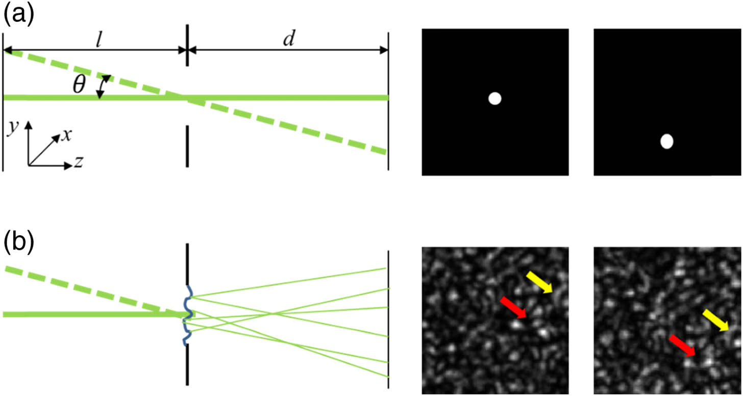
If the diameter of a laser beam illuminating an aperture is smaller than the aperture, the beam propagates as if no aperture exists. The tilt in the incident beam at an angle leads to the same amount of tilt in the output beam [see Fig. 1(a)]. Under the paraxial condition, the distortion in the beam spot on the observation plane is trivial, and the aperture can be considered as a shift-invariant system. Once we introduce a random phase distribution to the aperture—also called a random phase mask—we see speckles on the observation plane instead of a bright spot. Tilting the incident laser beam causes the entire speckle pattern to shift, as shown in Fig. 1(b), which is referred to as the memory effect—more specifically, the AME. While a single spot is considered in the shift invariance [Fig. 1(a)], the entire speckle pattern is used as the reference for speckle correlation in the memory effect [Fig. 1(b)].
Sign up for Photonics Research TOC. Get the latest issue of Photonics Research delivered right to you!Sign up now
Figure 1.Comparison of laser light incident upon an aperture (System 1) and a random phase mask (System 2) with no thickness. (a) Tilting the laser beam an angle (a shift of along the axis correspondingly) results in the same amount of tilt (a shift on the observation plane) in the output, as in a typical shift-invariant phenomenon. (b) Tilting the laser beam leads to a corresponding shift in the entire speckle pattern. The red and yellow arrows call attention to similar characteristics and their shifts.
For both systems, the light fields on the observation planes can be written as where represents the field incident upon the aperture plane, is a transmission function from the aperture plane to the observation plane, and is the aperture function. For a pure aperture, e.g., a diaphragm, where is the effective area of the aperture. For a random phase mask, where is a random function. The phase mask scrambles the wavefront, and a speckle pattern is therefore generated. Correlating the shifted speckle pattern with the original one at , a correlation curve can be obtained, and the full width at of the maximum of the curve is defined as the AME range. Considering the detected intensity distributions in Fig. 1(a) as special speckle patterns, we can also obtain a correlation curve. Within the shift-invariant range, i.e., one satisfying the paraxial approximation, the patterns in Fig. 1(a) are similar and correlated. The full width at of the maximum of this correlation curve is then determined by the shift-invariant range. If we take the random phase mask as a scrambled wavefront impinging on the unobstructed aperture, it is also a shift-invariant system, and its AME range is the same as its shift-invariant range. Thus, the memory effect can be considered high-order shift invariance. Regardless of the severity in the fluctuation in , the AME range of System 2 does not change, which means that single scattering itself is not responsible for the small range of the memory effect.
When inserting another aperture/mask into the optical path of System 2 to obtain Systems 3 and 4, as shown in Fig. 2, the field on the observation plane becomes where () is the th aperture function, is the transmission function from the first aperture plane to the second aperture plane, and is the transmission function from the second one to the observation plane. The two configurations of can be depicted in the same forms as Eqs. (2) and (3), respectively.
Figure 2.Comparison of light propagating through two screens in sequence. The second screen is (a) an aperture, referred to as System 3, and (b) a random phase mask, referred to as System 4.
For System 3, it is obviously a shift-invariant system; its shift-invariant range is the same as a system consisting of two unmasked apertures. For System 4, since Mask 2 has internal structures, a shift in the input wavefront on Mask 2 will result in a different output, breaking the shift invariance. For better understanding, we take the Fourier transform of Eq. (4) and obtain where is the convolution operator, is the Fourier transform of , and is the Fourier transform of . For System 3, , and Eq. (5) can be simplified as The Fourier transform of Eq. (1) is Comparing Eq. (6) to Eq. (7) reveals that obviously the AME range of System 3 is also the original shift-invariant range. For System 4, has a broad distribution, especially for a white-noise phase mask that has a zero lateral correlation length (to be discussed further) for which . Consequently, the original input wavefront is totally scrambled through Mask 2, decimating all memory effect as derived below.
If Mask 1 is just an unmasked aperture, will the memory effect remain? If , Eq. (5) can be simplified as Only when the incident light field is a normally incident plane wave, i.e., , does Eq. (8) share the same format as Eq. (7). Once the incident wavefront has an internal structure, tilting the incident light leads to a relative shift between the wavefront and the second phase mask after propagation, which introduces changes and damages the shift invariance. If the medium in which the light propagates has a negligible thickness, there is no relative shift between the wavefront and the cross section of a turbid medium when tilting the input. This observation explains how the thickness comes into play in the AME and how the incident plane in which the beam tilt pivot is located affects the range of the memory effect [17].
The intensity correlation function of two speckle patterns can be expressed as where denotes the ensemble average and . For a practical random phase Mask 2—typically a ground glass disk—its fluctuation can be modelled by a complex circular Gaussian random process with zero mean [18]. Then, the field correlation can be expressed as where and are the standard deviation of the height and the transverse correlation length of the ground glass disk, respectively, and is its refractive index. After derivation (see Appendix A), we obtain the AME range: Obviously, the AME range of the system is affected by the distance and the characteristics of the phase mask , which quantifies the relative roughness. For a white-noise Mask 2, , , there is no memory effect at all as stated above.
If we define and , Eq. (10) becomes According to the autocorrelation theorem [19], the spatial power spectral density (sPSD) of the ground glass phase mask can be written as where and is the Fourier transform of .
Here, we ask ourselves the following questions. How do we connect the phase mask model to a real scattering medium with some thickness? If the space between Planes 1 and 2 is filled with scattering medium, can we concentrate all the scattering effect onto Plane 2 and replace it with an equivalent phase mask?
We know that each occurrence of scattering has a phase function corresponding to an angular distribution of the intensity of the scattered light. A commonly used approximation is the Henyey–Greenstein phase function [20]: To obtain the angular spectrum of the total scattered light intensity, we need to know the weights of different scattering components and the phase function of each. According to Beer’s law, , after transmission through a thickness in a scattering medium, the weight (probability) of ballistic light is , where is the scattering coefficient. Next, we derive the weight for a singly scattered photon. Its path contains three parts: first, free propagation from position 0 to , where ; second, scattering at ; and third, free propagation from to . Thus, the probability of a single scattering event is a product of the probabilities of the three sub-events: . Since scattering can occur at any position between 0 and , is an integral over , which is calculated as . Similarly, the possibility for a photon to be scattered times after propagating over a distance in the medium can be expressed as The Henyey–Greenstein phase function is circularly symmetric; hence, there is no azimuth angle in Eq. (14). For a photon scattered times, its phase function is also circularly symmetric and can be calculated by the ()-times self-convolution of : The angular distribution of ballistic photons is .
Now, we can calculate the overall angular distribution of the scattered light intensity as After performing a transformation from coordinates to coordinates, where and are the spatial frequencies along the and axes, respectively, Eq. (13) becomes To replace the thick turbid medium with an equivalent phase mask, they should share the same sPSD, i.e., Eq. (18) should be equal to Eq. (17): If , Eq. (19) becomes which means that , i.e., the phase mask is flat with no phase fluctuation, and the AME range is the same as the shift-invariant range.
If is equal to the mean free path (MFP), i.e., , Eq. (19) becomes The weight of ballistic light decreases to . For singly scattered light, can be calculated from , and the AME range can be obtained on the basis of Eq. (11). Similarly, we can obtain the weights and AME ranges of doubly and multiply scattered light. Obviously, both the weight and the AME range decrease with the increasing scattering events. The entire AME range of an MFP-thick medium is the weighted sum of the ballistic light and different scattering components. However, the weights in the AME are not proportional to the weights in the angular distribution of intensity because of the nonlinearity of both Eqs. (11) and (19).
For other thicknesses, we can always fit the for different scattering components and calculate the corresponding AME ranges. As scattering times increase, the corresponding AME range decreases. The entire AME range is a weighted sum of all scattering components.
3. SIMULATION AND EXPERIMENTAL RESULTS
From the above derivations, it is clear that the DC component , i.e., the ballistic light, has an important contribution to the memory effect. On the basis of the physical picture, we design a new multiple-phase-mask model, which models a thick scattering medium as multiple phase masks evenly separated (optional) in sequence. The product of the interval between adjacent masks and the number of phase masks equals the medium thickness. In the conventional multiple-phase-mask model [13], several successive evenly spaced phase masks are applied, and light scattering is assumed to occur only at the masks. A single mask represents a single scattering event; therefore, the spatial frequency distribution of the mask is determined by only the phase function, and the distance between two adjacent masks is set to be the MFP. However, the memory effect of the conventional model is much smaller than that of a real scattering medium. Now, we know that the main problem of this model is the exclusion of ballistic light. By using Eq. (19) to generate a phase mask (see Appendix B for the workflow), we integrate more ballistic light into the simulation (see Appendix C for a comparison of the new and conventional phase mask models), and the simulated memory effect curve agrees well with the experimental results, as shown in Fig. 3. The angular distributions of scattered light intensity calculated using Eq. (17) are compared with the standard Monte Carlo (MC) simulation, in which scattered photons are classified according to their directions instead of positions. The results agree well, which means that Eq. (17) is an accurate description of the angular distribution of scattered light. The simulation in Fig. 3(c) shows that less scattered light has a larger AME range. A direct way to expand the AME range is to select less-scattered photons.
Figure 3.Simulation and experimental results. (a) Comparison of the normalized angular PSDs obtained from the MC simulation and Eq. (17) with different anisotropy factors . As decreases, the PSD broadens. Both curves peak at . The value of is slightly smaller than that obtained from the MC simulation at larger angles, which might be due to the truncation at when calculating . (b) AME curves obtained from the experiment (magenta curve, square markers), simulations with the conventional model (green solid curve), and our new model (black solid curve). (c) A comparison of AME curves with different scattering components including only singly scattered light (green solid curve), i.e., the conventional model, all scattering components integrated (black solid curve), i.e., the sPSD is obtained from the standard MC simulation, ballistic and the first six scattering components (magenta solid curve), and ballistic and only singly scattered light (blue solid curve).
In the experiment, the turbid sample is made of silicon microspheres, porcine gelatin, and distilled water with a scattering coefficient of and a thickness of 1 mm. The microspheres have an average diameter of 2.5 μm and a refractive index of 1.45, and the refractive index of gelatin is 1.33. According to the Mie theory, the anisotropy factor . The AME curve was measured by scanning a time-reversed focus (see Appendix D for a schematic figure of the principle) [8,17,21].
4. DISCUSSION AND CONCLUSION
The relative shift between the wavefront and the scattering medium is the reason for the break of the AME. When the correlation lengths of the wavefront and equivalent phase mask are smaller, the AME range is smaller. The translation memory effect, i.e., the shift memory effect, is also influenced by the relative shift between the wavefront and the cross section in the medium. Essentially, they are the same. With the aid of the new picture, we can explain the phenomena of different AME ranges for turbid media with the same physical thickness or optical thickness. For a thick turbid medium, the AME range of multiply scattered light is small; the main contribution to a measurable AME range is the ballistic and singly scattered components. To expand the AME range, we can select more ballistic and singly scattered light in detection. Compared to the conventional multiple phase mask models, the new one is closer to simulate coherent wavefront propagation in scattering media.
In summary, we present a new physical picture for the optical memory effect, whose validity is not limited by the thickness of the medium. In this picture, the memory effect and shift invariance are united with the intensity correlation. We depict the role of thickness, scattering times, and anisotropy factor, analyze the AME ranges of different scattering components, and derive a new equation to estimate the AME range, which is affected by the characteristics of the random phase masks and the distance. In other words, the AME range of a thick turbid medium is not determined just by its thickness but also by the scattering coefficient and anisotropy factor. Based on the new physical picture, we modify the traditional random phase mask model to a more physical one. The new picture and more flexible new model provide powerful tools for further study of phenomena based on the memory effect, and wavefront sensitive techniques, such as wavefront shaping [22–24], optical phase conjugation [25–27], and optical trapping [28] in/through scattering media. It will impact biomedical imaging, seeing through clouds, photodynamic therapy, and light manipulation in/through turbid media.
APPENDIX A: DERIVATION OF THE SPECKLE CORRELATION AND AME RANGE
Substituting Eq. (4) into Eq. (9), we obtain where is a normal incident plane wave and is the tilted plane wave with a tilt angle . Since the two phase masks are independent, the ensemble average can be separated. For a random function , if satisfies a complex circular Gaussian distribution with zero mean [18], then and where , is a field correlation function. If each point in phase Mask 1 is independent, we have and Thus, Eq. (A1) becomes When the diameter of the first aperture approaches infinity, we obtain With the assumption that each point in phase Mask 2 is independent, Eq. (A9) becomes Neglecting the constant coefficient, For phase Mask 2 with an aperture radius of , we have The sinc function determines the speckle size on the observation plane. The first and second terms constitute a constant. Only the third term is related to a variable coefficient of . We define it as which was also called the correlation of the intensity fluctuation in ghost imaging [29]. Obviously, has an impulse only at ; thus, the range of the memory effect is zero.
For a common phase mask such as a ground glass disk, , where and are the standard deviation of the height and the transverse correlation length, respectively, is its refractive index [30–32], and the radius of Aperture 2 is . Then, the counterpart of Eq. (A13) is The coefficient is a Gaussian function of , and the width at can be derived from Under the paraxial approximation, is sufficiently small such that , and Eq. (A15) becomes Therefore, the AME range is It is inversely proportional to both the thickness and the average ratio of the longitudinal size to the transverse size of the grains of a typical ground glass disk .
APPENDIX B: WORKFLOW FOR GENERATING A PHASE MASK
By performing a transformation from coordinates to coordinates for Eq. (19), we obtain the spatial power spectral density of the phase mask . Then, the domain mask can be obtained by performing a Fourier transform of . We know that the domain presentation of a phase mask must be phase only; in other words, the absolute value of a phase mask must be uniform in the space, which is the demand of the time-reversal symmetry of a pure scattering medium. However, the Fourier transform of does not guarantee a phase-only mask in the domain. Fortunately, the total angular distribution function limits only the amplitude of , because represents only the intensity distribution of the scattered light. Thus, can be assigned any phase distribution, which allows us to find a special phase distribution that leads to a phase-only mask . This is a typical problem that can be solved by the Gerchberg–Saxton (G-S) algorithm [33] with the detailed algorithm workflow shown in Fig. 4.
Figure 4.Workflow for generating the real-domain phase-only masks using the G-S algorithm. and are the Fourier-domain expressions of the mask. and are the real-domain expressions of the mask. The algorithm starts from with an initial value of , where is the envelope of its amplitude and is a random phase distribution. After several iterations, the algorithm will converge; then, is the desired phase-only mask.
APPENDIX C: COMPARISON OF THE NEW AND CONVENTIONAL PHASE MASK MODELS
By considering more ballistic light, the new multiple-random-phase-mask model has a larger AME range than the conventional one, as shown in Fig. 5. In the new model, the distance between two adjacent masks is not necessarily the MFP of the scattering medium; instead, it can be flexibly adjusted according to computational resources and the requirements for precision. In the simulation, we set the distance to be equal to or half of the MFP and use angular spectrum diffraction theory to calculate the free propagation of light between two adjacent masks. The consistency between the blue and orange curves in Figs. 5(f) and 5(g) verifies the reliability and self-consistency of the new phase mask model.
Figure 5.Comparison between the conventional phase mask model and our new phase mask model for a scattering medium with . (a) Phase map of the conventional mask. (b) and (c) Phase maps of our new masks when the interval is set to be the MFP and 0.5 times the MFP, respectively. (d) Phase distributions of the three masks. Compared to the conventional mask in (a), which has a full phase modulation depth, the new masks in (b) and (c) have shallower modulation depths, which allow more ballistic light to pass through. When the interval between adjacent masks is smaller, the modulation depth will be shallower. (e) Spatial frequency distributions of the three masks. The conventional mask has a very smooth spatial frequency distribution, but for the new masks, there is a sharp peak at zero frequency, which is caused by the delta function of the ballistic light. (f) and (g) Memory effect curves for 0.5 mm and 1 mm thick scattering media with an MFP of 0.1 mm and modelled by the conventional phase mask model (purple curve) and our new model (blue curve for , orange curve for ).
APPENDIX D: SCHEMATIC FIGURE OF THE PRINCIPLE OF SCANNING A TIME-REVERSED FOCUS
The schematic of the principle of scanning a time-reversed focus is shown in Fig. 6.
Figure 6.Principle of scanning a time-reversed focus. (a) A point source is placed in front of a scattering medium, and a wavefront of the transmitted light through the medium is recorded by the digital optical phase conjugation (DOPC) system. (b) The point source is removed, and a phase-conjugated wavefront is generated by the DOPC system to create a time-reversed focus at the original position of the point source. By adding a phase ramp to the phase-conjugated wavefront, we can scan the focus along a desired direction.