
Weixing Li, Jing Lu, Ke Xiao, Wei Ji. Recent Developments in Fluorescence-Guided Cryogenic Focused-Ion-Beam Milling[J]. Chinese Journal of Lasers, 2023, 50(21): 2107102
- Chinese Journal of Lasers
- Vol. 50, Issue 21, 2107102 (2023)
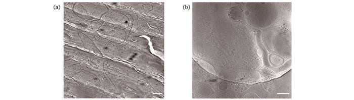
Fig. 1. Biological samples cryo-fixed in vitreous ice (scalebar: 200 nm). (a) TEM image of lamella of U2OS cell vitrified using high pressure freezing; (b) TEM image of PC12 cell vitrified using plunge freezing
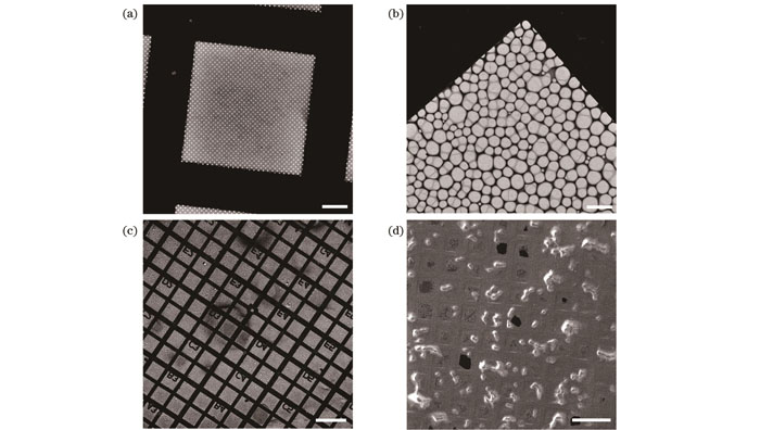
Fig. 2. EM grids for plunge freezing of cells. (a) Quantifoil grid with regular circular holes (scalebar: 200 μm); (b) lattice grid with irregular holes (scalebar: 200 μm); (c) lattice grid with coordinate markers (scalebar: 200 μm); (d) lattice grid containing HeLa cells (scalebar: 200 μm)
Fig. 3. Commercial instruments for plunge freezing. (a) Vitrobot from ThermoFisher; (b) EM GP from Leica; (c) Cp3 from Gatan
Fig. 4. Commercial dual-beam FIB/SEMs. (a) Crossbeam dual-beam FIB/SEM from Zeiss; (b) Aquilos dual-beam FIB/SEM from ThermoFischer; (c) Amber dual-beam FIB/SEM from Tescan
Fig. 5. Cryostage system from Quorum. (a) Cryostage module; (b) cryotrap module; (c) cryogenic sample transfer module equipped with magnetron sputter coating function
Fig. 6. Autogrid and sample holder. (a) EM grid mounted in Autogrid; (b) cryostage sample holder containing Autogrid samples
Fig. 7. FIB milling of vitrified cells (scalebar: 5 μm). (a) FIB image of HeLa cells vitrified on grid with part to be cut off shown in dashed box; (b) FIB image of cell lamella after milling; (c) SEM image of cell lamella after milling; (d) SEM image of cell lamella with micro-expansion joints (arrows)
Fig. 8. Principle of fluorescence-guided cryo-FIB milling (scalebar: 10 μm). (a) FIB image of HepG2 cells with five fluorescent beads selected for image registration shown by circles; (b) light microscopy image of Fig. 8(a) with five fluorescent beads in Fig. 8(a) shown by circles and selected interest target shown by arrow; (c) superimposition of FIB and light microscopy images after image registration with target chosen in Fig. 8(b) shown by arrow
Fig. 9. Schemes of fluorescence-guided cryo-FIB milling (image source: www.nanoscience.com). (a) Pipelined scheme; (b) integrated scheme
Fig. 10. Commercial optical cryostat and imaging systems by cryo-FLM. (a) HCS621GXY Cryostat from Instec; (b) CMS196 cryostat from Linkam; (c) MicrostatN cryostat from Oxford Instruments; (d) ST500 cryostat from Janis; (e) Zeiss confocal cryo-imaging system equipped with Linkam cryostat; (f) Leica cryo-imaging system equipped with self-developed cryostat
Fig. 11. Commercial integrated cryo-FLM-FIB/SEM systems. (a) Widefield FLM module METEOR from Delmic for FIB/SEM; (b) FIB/SEM equipped with METEOR; (c) ThermoFisher Aquilos 2 FIB/SEM with self-developed widefield fluorescence imaging module iFLM
Fig. 12. ELI-TriScope system and application[58]. (a) 3D schematic illustration of ELI-TriScope system; (b) in situ structure of centriole in HeLa cells
Fig. 13. CLIEM system and application[60]. (a) 3D schematic illustration of CLIEM system; (b) in situ structure of contact site between mitochondria (M) and lipid droplet (LD) with tethering structures discovered on interaction surface shown by arrows and scalebar is 50 nm; (c) rendering of HeLa cell centriole and surrounding structure
|
Table 1. Comparison of different fluorescence-guided FIB milling strategies

Set citation alerts for the article
Please enter your email address
© Copyright 2018-2021 | Chinese Laser Press. All Rights Reserved 沪ICP备15018463号-20