
Zhao Zhang, Gaoyuan Li, Yonglei Liu, Haiyun Wang, Bernhard J. Hoenders, Chunhao Liang, Yangjian Cai, Jun Zeng. Robust measurement of orbital angular momentum of a partially coherent vortex beam under amplitude and phase perturbations[J]. Opto-Electronic Science, 2024, 3(1): 240001
- Opto-Electronic Science
- Vol. 3, Issue 1, 240001 (2024)
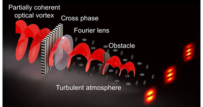
Fig. 1. Schematic diagram probing the OAM of a partially coherent optical vortex via a cross-phase.
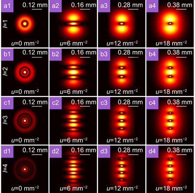
Fig. 2. The evolution for the modulus of the degree of coherence of a partially coherent Laguerre Gaussian beam carrying different topological charges in the focal plane versus the values of u.
Fig. 3. The schematic diagram of the pseudo-mode superposition principle and cross-phase induced spatial-coherence structure splitting. (a ) The intensity distribution of each individual Laguerre Gaussian sub-mode embedded with cross-phase for u=12 mm−2 and l=1 in the source plane. (b ) The intensity distribution of each individual Laguerre Gaussian sub-mode embedded with cross-phase for u=12 mm−2 and l=1 in the focal plane. (c ) The average intensity of a partially coherent Laguerre Gaussian beam embedded with cross-phase for u=12 mm−2 and l=1 in the focal plane. (d ) The distribution of modulus of the degree of coherence of a partially coherent Laguerre Gaussian beam embedded with cross-phase for u=12 mm−2 and l=1 in the focal plane. The green line is used to mark the main lobe structure.
Fig. 4. The distributions of modulus of the degree of coherence of partially coherent Laguerre Gaussian beams without cross-phase in the focal plane when obstacles with different occlusion angles α are placed in the source plane. The illustrations in the lower right corner represents the corresponding intensity distribution in the source plane when obstacles with different occlusion angles α are placed in the source plane.
Fig. 5. The distributions of modulus of the degree of coherence of partially coherent Laguerre Gaussian beams with cross-phase (u=12 mm−2) in the focal plane when obstacles with different occlusion angles α are placed in the source plane. The illustrations in the lower right corner represents the corresponding intensity distributions in the source plane when obstacles with different occlusion angles α are placed in the source plane.
Fig. 6. (a1 –a4 ) The distributions of modulus of the degree of coherence of partially coherent Laguerre Gaussian beams without cross-phase in the focal plane in the presence of turbulence. (b1 –b4 ) The distributions of modulus of the degree of coherence partially coherent Laguerre Gaussian beams without cross-phase in the focal plane in the presence of an obstacle with occlusion angle α=π/2 and turbulence. (c1 –c4 ) The distributions of modulus of the degree of coherence of partially coherent Laguerre Gaussian beams with cross-phase in the focal plane in the presence of turbulence. (d1 –d4 ) The distributions of modulus of the degree of coherence of partially coherent Laguerre Gaussian beams with cross-phase in the focal plane in the presence of an obstacle with occlusion angle α=π/2 and turbulence. The illustrations in the lower right corner represents the corresponding intensity distributions in the source plane obstructed by obstacles with different occlusion angles α.
Fig. 7. (a ) Experiment setup for the generation of a partially coherent Laguerre Gaussian beam with a controllable cross-phase and the measurement of the distribution of modulus of the degree of coherence of this beam, when obstructed by an obstacle in the far field propagation in free space (without hot plate) as well as in a turbulent atmosphere (with hot plate). Laser, a He-Ne laser with wavelength 632.8 nm; NDF, neutral density filter; LP, linear polarizer; RGGD, rotating ground glass disk; L1, L2, L3, L4, L5, thin lenses; GAF, Gaussian amplitude filter; BS, beam splitter; SLM, spatial light modulator; CA, circular aperture; SP, source plane; HP, hot plate; CCD, charge-coupled device. (b ) Measured atmospheric refractive index structure constant
Fig. 8. The experimental results for the modulus of the degree of coherence of a partially coherent Laguerre Gaussian beam carrying a cross-phase for u=12 mm−2 in the focal plane. (a1 –a4 ) The experimental results for the cases with different topological charges l when the obstacle is removed. (b1 –b4 ) The experimental results for the cases with different topological charges l when the obstacle with occlusion angle α=π/3 is placed in the source plane. (c1 –c4 ) The experimental results for the cases with different topological charges l when the obstacle with occlusion angle α=π/2 is placed in the source plane.
Fig. 9. Experimental results for the effect of the obstacle and turbulence on the modulus of the degree of coherence of a partially coherent Laguerre Gaussian beam carrying a cross-phase in the focal plane for u=12 mm−2. (a1 –a4 ) The experimental results for the cases in the presence of turbulence with temperature T=50 °C when the obstacle is removed. (b1 –b4 ) The experimental results for the cases in the presence of turbulence with temperature T=50 °C when the obstacle with occlusion angle α=π/3 is placed in the source plane. (c1 –c4 ) The experimental results for the cases in the presence of turbulence with temperature T=50 °C when the obstacle with occlusion angle α=π/2 is placed in the source plane.
Fig. 10. Experimental results for the effect of the temperature on the modulus of the degree of coherence of a partially coherent Laguerre Gaussian beam carrying a cross-phase for l=2 and u=12 mm−2 in the focal plane. (a1 –a3 ) The experimental results for the cases in the presence of turbulence with temperature T=75 °C when obstacles with different occlusion angles α are placed in the source plane. (b1 –b3 ) The experimental results for the cases in the presence of turbulence with temperature T=100 °C when obstacles with different occlusion angles α are placed in the source plane.

Set citation alerts for the article
Please enter your email address
© Copyright 2018-2021 | Chinese Laser Press. All Rights Reserved 沪ICP备15018463号-20