
Chao Wang, Hui Wei, Youen Jiang, Jiangfeng Wang, Zhi Qiao, Jiangtao Guo, Wei Fan, Xuechun Li, "VCSEL-pumped Nd:YAG laser with 95 W average power and user-selectable nanosecond pulses," Chin. Opt. Lett. 14, 121402 (2016)
- Chinese Optics Letters
- Vol. 14, Issue 12, 121402 (2016)
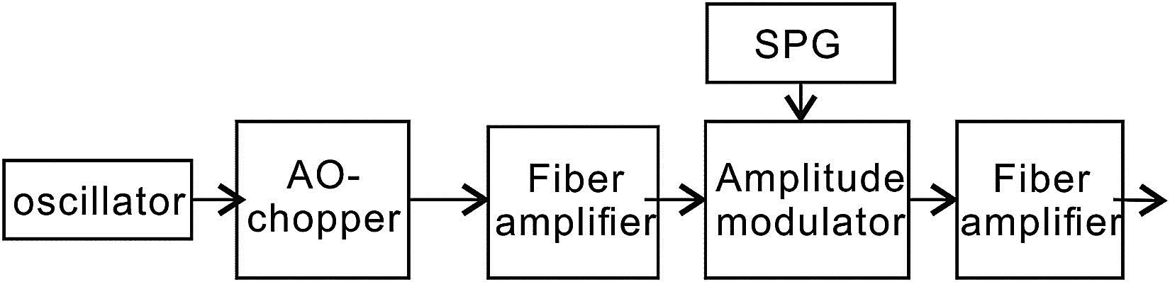
Fig. 1. Functional block diagram of the seeder.
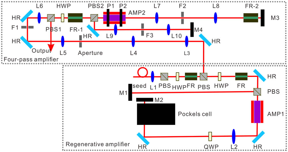
Fig. 2. Schematic of the regenerative amplifier and the four-pass amplifier, which includes Nd:YAG laser heads (AMP1 & AMP2), mirrors (M1–M4), 45° reflectors (HR), lenses (L1–L10), polarization beam splitter (PBS), Faraday rotators (FR), half wavelength plates (HWP), beam focuses (F1∼3), the first principal plane of the rod (P1), and the second principal plane of the rod (P2).
Fig. 3. Pumping configuration of the module used in the four-pass amplifier.
Fig. 4. Gain distribution over the cross section of the rod; the red line and the blue line represent the gain distribution along the horizontal and vertical center line of the cross section of the rod.
Fig. 5. Principle of the birefringence compensation.
Fig. 6. Output energy versus input energy of the four-pass amplifier.
Fig. 7. Output beam profile measured on the image plane.
Fig. 8. Wavefront distribution measured on the image plane.
Fig. 9. Temporal profiles for (a) 2, (b) 4, and (c) 6 ns pulses, respectively. The dashed line, the dotted line, and the solid line represent the pulse shape of the seed, the regenerative amplifier, and the four-pass amplifier, respectively.


Set citation alerts for the article
Please enter your email address

© Copyright 2018-2021 | Chinese Laser Press. All Rights Reserved 沪ICP备15018463号-20