
Liangwei Sun, Qing Luo. Design and simulation of interferometer for synchrotron radiation beam size measurement[J]. High Power Laser and Particle Beams, 2021, 33(8): 084002
- High Power Laser and Particle Beams
- Vol. 33, Issue 8, 084002 (2021)
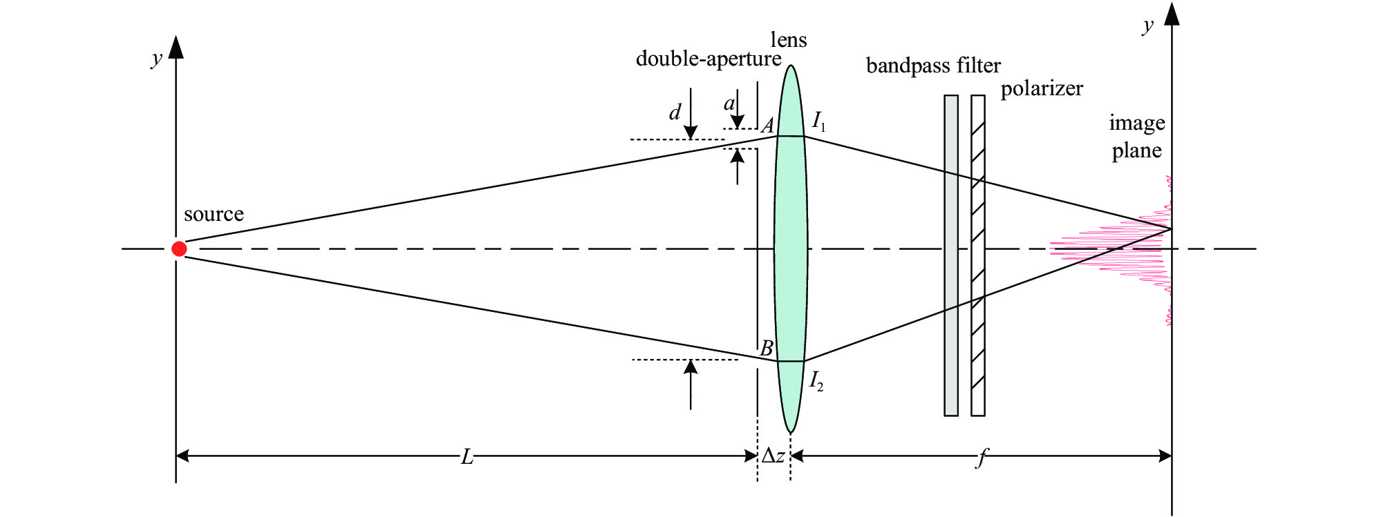
Fig. 1. Schematic diagram of interferometer

Fig. 2. Schematic of the optical system of the interferometer
Fig. 3. Change of beam size measurement error with coherence
Fig. 4. Change of coherence with the slit separation
Fig. 5. Schematic of RC focusing mirror
Fig. 6. Relationship between the distance between the light source and the slit and the degree of coherence
Fig. 7. Simulation diagram of interferometer
Fig. 8. Vertical interference fringes and fitting graph (L =30 m, d =16 mm)
Fig. 9. Horizontal interference fringes and fitting graph (L =40 m, d =18 mm)
Fig. 10. Data points and fitted curve
Fig. 11. Effect of intensity imbalance factor on coherence and beam size
| ||||||||||||||||||||||
Table 1. Structure parameters of interferometer
|
Table 2. Comparison of the results of interferometer optical path quality evaluation
|
Table 3. Results of simulation
|
Table 4. Error calculation table
|
Table 5. Parameters of vertical interferometer and measurement standard deviation

Set citation alerts for the article
Please enter your email address
© Copyright 2018-2021 | Chinese Laser Press. All Rights Reserved 沪ICP备15018463号-20