State Key Laboratory of Precision Measurement Technology and Instruments, Department of Precision Instrument, Tsinghua University, Beijing 100084, China
Tong Yang, Jun Zhu, Guofan Jin, "Compact freeform off-axis three-mirror imaging system based on the integration of primary and tertiary mirrors on one single surface," Chin. Opt. Lett. 14, 060801 (2016)
Copy Citation Text
In this Letter, a novel and compact freeform off-axis three-mirror imaging system and its detailed design method are proposed. The primary mirror and tertiary mirror of the system have the same surface analytical expression and they are integrated on one single freeform surface. In this way, the alignment process is made much easier due to the much fewer degrees of freedom. In addition, the difficulty and cost for the data handling, fabrication, and testing of the freeform surfaces and system can also be significantly reduced in some cases, especially compared with the configuration having multiple surfaces of different expressions integrated on one monolithic substrate. The final system has a 100 mm effective focal length and a field of view. The modulation transfer function of the system is close to the diffraction-limit.
Compared with refractive systems, reflective optical systems have many advantages. They are free from chromatic aberrations, which means that they can have high and uniform performance over a broad spectral band. In addition, reflective systems have the advantages of light weight, high transmission, radiation resistance, and thermal stability[1–4]. However, the central obscuration in traditional coaxial reflective systems greatly limits the resolution, energy concentration, and field of view (FOV)[5]. As a consequence, researchers have proposed the off-axis reflective systems in order to eliminate the obscurations[1,2,6,7]. However, the possible biased FOV and off-axis aperture as well as the unconventional configuration greatly increase the design difficulty. In addition, as the rotational symmetry of the optical system is broken many unconventional and asymmetric aberrations are induced, such as the field-constant coma and astigmatism, field-asymmetric astigmatism, field-conjugate astigmatism, and other aberrations with unconventional field dependence[8–11]. It is difficult to correct these aberrations induced by asymmetry using traditional rotationally symmetric surfaces such as spherical and aspherical surfaces. Therefore, the image quality is limited when large FOV or/and low F-number are required.
A method for getting a higher performance while operating off axis is to use freeform optical surfaces. Freeform surfaces can offer more degrees of design freedom in optical design[12,13]. In addition, they can generate unconventional aberrations that are consistent with the aberrations induced by the asymmetric configuration discussed above[8–11,14,15]. Therefore, freeform surfaces are very useful and suitable for the off-axis system design. In recent years, with the development of the advanced manufacture technologies[16,17], freeform surfaces have been successfully used in unobscured off-axis reflective systems design[18–26]. However, the cost and difficulty of alignment and surface testing are significantly increased due to the asymmetric surface shape and system structure. To solve this problem, Zhu et al.[18,25,26] have proposed the designs of freeform off-axis three-mirror or four-mirror systems based on the integration of two different mirror surfaces on one single monolithic substrate. In this way, multiple optical surfaces can be fabricated simultaneously on a common substrate. With proper auxiliary surfaces or reference planes[18,26], the alignment difficulty can be significantly reduced due to the much fewer degrees of freedom (DOFs). However, as the multiple surfaces on one single element are in fact independent with each other and they have different analytical expressions, the difficulty and cost for testing remains the same. For example, if computer-generated hologram (CGH) is used for testing the freeform surface, multiple CGH elements are still needed for the multiple different freeform surfaces. More seriously, the integration of multiple surfaces with different analytical expressions greatly increases the complexity and difficulty for the data handling and the fabrication[26]. As a consequence, the realization of this kind of freeform system still requires a high cost and long duration, and sometimes cannot justify even the efforts for the conventional designs. If multiple freeform surfaces in the imaging system can be further integrated on one single optical surface with the same analytical expression, the alignment difficulty can also be significantly reduced compared with the system having separated mirrors. More importantly, the fabrication and testing of multiple mirror surfaces is simplified into the fabrication and testing of one single surface. In this way, for some cases, the difficulty and cost for the fabrication, testing, and alignment of the multiple freeform mirrors can be reduced, especially compared with the design forms when multiple surfaces with different analytical expressions are integrated[18,25,26]. It is both an interest and a challenge to design freeform imaging systems based on the integration of multiple mirrors on one single surface.
In this Letter, a novel and compact design of a freeform off-axis three-mirror imaging system has been proposed. The goal of the design is to integrate the primary mirror (M1) and the tertiary mirror (M3) on one single surface with the same freeform surface analytical expression. This kind of freeform system, to the best of the authors’ knowledge, has not been reported before. Detailed design procedures are demonstrated. The system specifications are listed in Table 1.
Sign up for Chinese Optics Letters TOC. Get the latest issue of Chinese Optics Letters delivered right to you!Sign up now
Parameter
Specification
FOV
4°×3°
F-number
2.5
Effective focal length
100 mm
Entrance pupil diameter
40 mm
Configuration
Off-axis three-mirror
Wavelength
8–12 μm
Table 1. Specifications of the Unobscured Off-Axis System
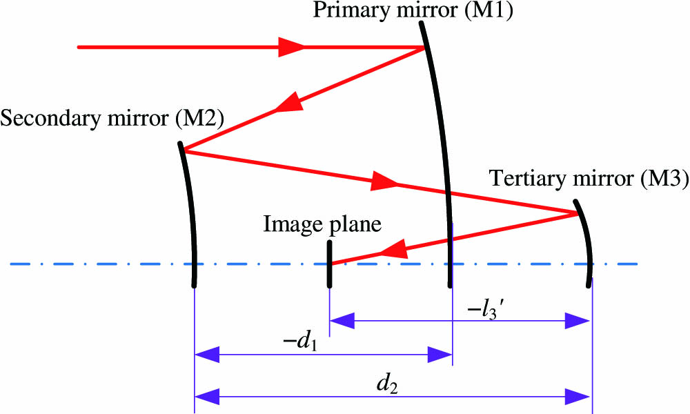
The first step of designing the off-axis unobscured system is to generate a coaxial three-mirror system using spheres. As shown in Fig. 1, based on the paraxial optical theory for a coaxial three-mirror system, the formulae between the system optical power, surface curvatures, and the distances between the surfaces can be written as[18]where is the optical power of the whole three-mirror system; , , are the surface curvatures of the three mirrors, respectively; are the distances between M1 and M2 (secondary mirror), M2 and M3, M3 and the image plane, respectively. The detailed derivations of Eqs. (1) and (2) can be found in Ref. [18]. In order to make M1 and M3 be the same single surface with the same surface expression, M1 and M3 need to be at the same position . Their surface curvatures have to be equal . In this way, Eqs. (1) and (2) can be simplified as Based on given system specifications, . Proper distances between the mirrors have to be maintained. Here, we take . Then, the following solution can be calculated using Eqs. (3) and (4): , , and . The external aperture stop of the system is before M1. The optical layout of the coaxial system is shown in Fig. 2.
The next design step of the system is to make this coaxial design unobscured. Here, the off-axis aperture and the biased FOV are used simultaneously. The aperture stop goes off axis in the direction for 65 mm. The input FOV is biased for 12° in the direction, which means that the central field of the off-axis system is (0°, 12°). Furthermore, surfaces in the system can be tilted to contribute to obscuration elimination. Tilting M1 or M3 seems to be a good choice. However, tilting M1 or M3 alone will make M1 and M3 be different surfaces. So, M2 is chosen to be tilted and it is tilted in the way to redirect the light after M3 to travel across the optical path between M1 and M2. Therefore, the total volume of the system is made small and the system configuration is very compact. The layout of the unobscured system is shown in Fig. 3. Note that the image plane of the system has been shifted in the direction to find the best focus. This system is taken as the starting point for further optimization.
Figure 3.Layout of the unobscured system. This system is taken as the starting point for further optimization.
The final design step is to optimize the starting point in the optical software. In this Letter, the optimization was conducted in CODE V[27]. As the system is symmetric about the YOZ plane, only half of the full FOV (0 and fields) is considered in the optimization. At the beginning stage, six fields are sampled, which are (0°, 12°), (0°, 13.5°), (0°, 10.5°), (2°, 12°), (2°, 13.5°), and (2°, 10.5°), respectively. The error function type used in the optimization is the default transverse ray aberration type in CODE V. As the system has a special off-axis nonsymmetric configuration, and it consists of nonsymmetric freeform surfaces, conventional distortion control methods employed in the coaxial system design are no longer feasible. In fact, the control of the distortion is equivalent to the control of the image height. As the required effective focal length and FOV of the system have been given in advance, the ideal equivalent image height for one specific field relative to the central field can be calculated based on the equations where and are the equivalent image height of this field in the and directions relative to the central field, respectively; is the effective focal length of the system; is the central field among the full FOV. The central field in this design is . and are the actual and coordinates of the chief ray on the image plane for the field; and are the actual and coordinates of the chief ray on the image plane for the central field . These coordinates can be obtained using the real ray trace data in CODE V. In this way, we can use the actual imaging coordinates on the image plane of the chief rays for different fields to control the distortion of the system.
The special off-axis nonsymmetric configuration of the system also requires the special constraints during the optimization in order to eliminate the obscuration of light. As shown in Fig. 4, is the distance from the bottom edge of the aperture stop to the bottom marginal ray of field (0°, 10.5°) after M3. is the distance from the top edge of the image plane to the bottom marginal ray of field (0°, 13.5°) from the object space. and can be used to control the light obscuration induced by the aperture stop and the detector. is the distance from the bottom edge of the image plane to the bottom marginal ray of field (0°, 13.5°) after M1. is the distance from the top edge of M2 to the top marginal ray of field (0°, 13.5°) after M3. and can be used to control the light obscuration induced by M2 and the detector. In order to make the M1-M3 element small in the direction, the distance between points and [the intersection points of the bottom marginal ray for the (0°, 10.5°) field with M1 and M3] in the direction is controlled. Furthermore, to reduce the size of the system in the direction, the distance between points and [the intersection points of the chief ray for the central field (0°, 12°) with M2 and M3] in the direction is controlled. Note that the aperture position (top or bottom) of a ray is always consistent with the definition at the aperture stop (entrance pupil). The control of the above distances can be achieved by adding user-defined constraints in CODE V. The macro functions offered by the software can be used in the constraints.
Figure 4.Constraints to eliminate the light obscuration and to control the size of the system.
The surface type of the freeform surfaces for both the M1-M3 surface and the M2 surface chooses to be XY polynomials, which are kinds of simple and effective nonrotationally symmetric freeform surfaces. In this Letter, the surfaces are up to the 5th order. Since the optical system is symmetric about the YOZ plane, only the even items of in XY polynomials are used, where is the curvature of the surface, is the conic constant, and is the coefficient of the terms. During the optimization process, to make M1 and M3 be the same single freeform surface with the same analytical expression, the decentered and tilted value as well as the surface coefficients of M3 are constrained to be equal, with the same parameters of M1. This can be done by setting the surface pickup in CODE V.
A successive optimization strategy is employed here in which the surface coefficients are added as variables successively in an increasing order. First, the surface curvatures as well as the decenter and tilt values for both the M1-M3 surface and the M2 surface are set as variables. After optimization, a decentered and tilted reflective spherical system with a much improved image quality over the starting point is obtained. Then, the conic constant for both of the surfaces are added as variables and the system is further optimized. Then, the 2nd-order XY polynomial coefficients ( and ) are set as variables. Next, the 3rd-order XY polynomial coefficients ( and ) are set as variables. Then, the 4th-order XY polynomial coefficients (, and ) are added as variables. Finally, the 5th-order XY polynomial coefficients (, , and ) are set as variables. During this optimization process, stronger constraints on the system structure and distortion depicted previously are gradually employed. More field points (total of 15 field points) are used at the final stage of the optimization. The changes in the average RMS wavefront error after adding different variables during the optimization process are given in Fig. 5. From Fig. 5, we can see that the improvement of the image quality is significant. This result validates the feasibility and effectiveness of the proposed design strategy. It should be noted that the constraints to control the distortion and the system structure as well the optimization method depicted above are not restricted to this design. The method has generality to a certain extent for all freeform imaging system design.
Figure 5.Change in the average RMS wavefront error after adding different variables during the optimization process.
The optical layout of the final design result is shown in Fig. 6. The size of the M1-M3 surface is about . The size of the M2 surface is about . The modulation transfer function (MTF) of the system is close to the diffraction limit, as displayed in Fig. 7. The RMS wavefront error of the system is shown in Fig. 8; the average value is at a 10 μm wavelength over a 5° diagonal FOV. The distortion grid of the system is given in Fig. 9. The above results show that good performance was achieved. The coefficients of the freeform surfaces are listed in Table 2.
In conclusion, a novel and compact freeform off-axis three-mirror imaging system is proposed. The primary mirror and tertiary mirror of the system are integrated on one single freeform surface with the same surface expression. The alignment difficulty can be significantly reduced compared with the system having three separated mirrors. More importantly, compared with the cases when multiple surfaces with different analytical expressions are integrated (as given in Refs. [18,25,26]), the fabrication and testing of multiple mirror surfaces (primary and tertiary mirrors) are simplified into the fabrication and testing of one single surface. Compact system configuration and excellent performance are achieved. The final system operates at an F-number of 2.5 with a 100 mm effective focal length and FOV. A detailed starting point design and the optimization methods are demonstrated.
Tong Yang, Jun Zhu, Guofan Jin, "Compact freeform off-axis three-mirror imaging system based on the integration of primary and tertiary mirrors on one single surface," Chin. Opt. Lett. 14, 060801 (2016)