
Ping Li, Jun Zhang, Xiaofeng Wei. Plasma optics technologies: State of the art and future perspective[J]. High Power Laser and Particle Beams, 2020, 32(1): 011008
- High Power Laser and Particle Beams
- Vol. 32, Issue 1, 011008 (2020)
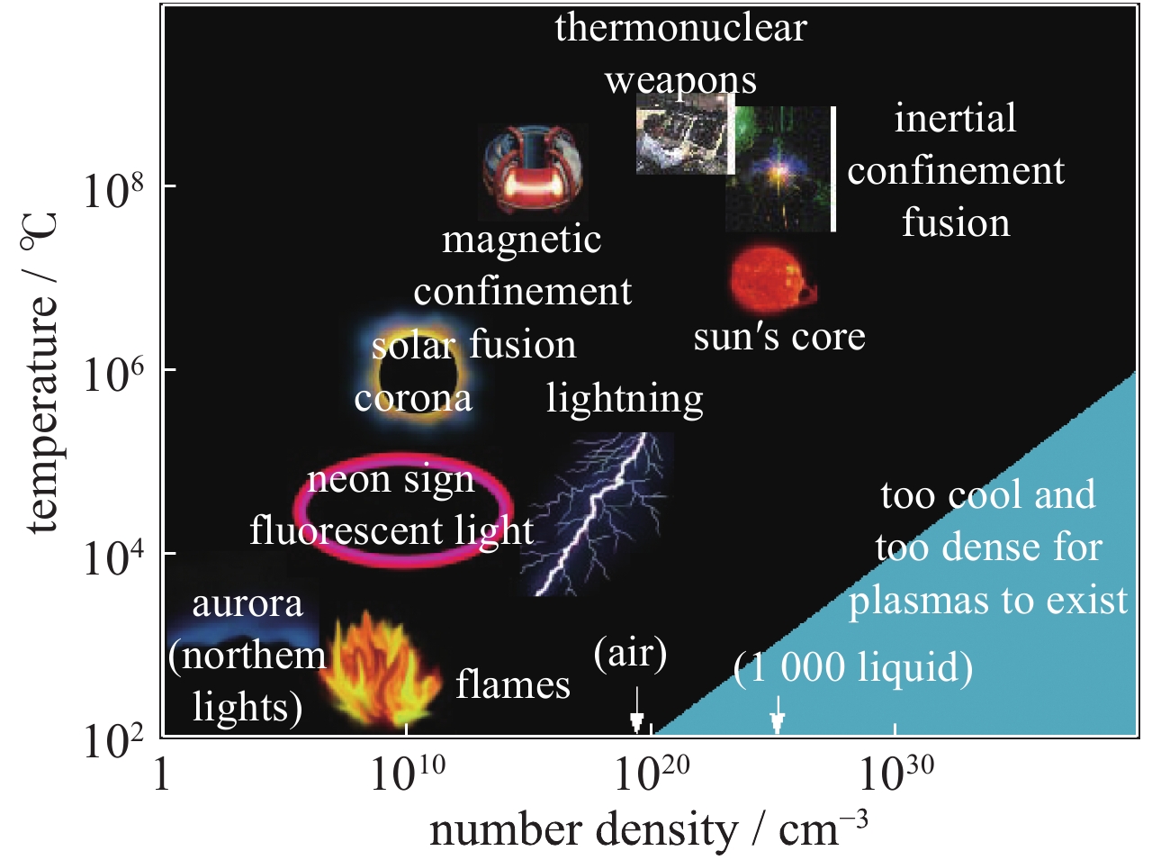
Fig. 1. Temperature and density range of typical plasma
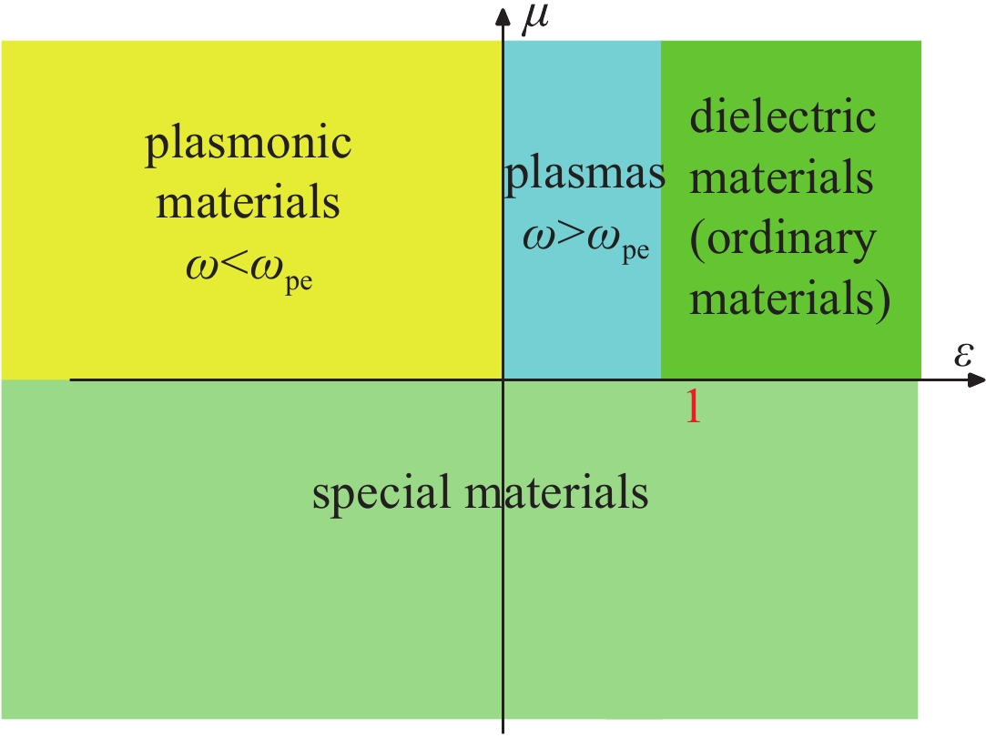
Fig. 2. Area division of distribution of permittivity and permeablity of materials
Fig. 3. Schematic diagram of PEPC
Fig. 4. Schematic diagram of low loss PEPC based on DKDP crystal
Fig. 5. Design diagram of reflective PEPC
Fig. 6. Basic principle of laser amplification based on plasma medium
Fig. 7. (a) The gas-filled balloon target is used to create a uniform plasma to amplify a single seed beam (red) by combination of eight pumping beams (yellow), (b) the incident power of all the beams
Fig. 8. Laser pulse-shape conditioning with a double plasma-mirror (DPM)
Fig. 9. Temporal profile of the laser pulses delivered by a 10 TW, 60 fs laser system, in logarithmic scale, with and without DPM
Fig. 10. (a) Experimental setup for tight focusing of ultrahigh-intensity laser pulses by low F -number confocal EPM. (b) Focal spot provided by the conventional F /2.7 output. (c) Focal spot in the output of the F /0.4, images are in common logarithm scale
Fig. 11. (a) Schematic diagram of cross beam interaction in plasma. (b) Excitation characteristics of cross beam energy transfer and phase shift
Fig. 12. Conceptual design of plasma polarizer and plasma wave plate
Fig. 13. The extreme Faraday effect of strongly magnetized plasma
Fig. 14. Schematic of the target arrangement to study the interaction of the PII-beam with a solid target
Fig. 15. Schematic of a plasma optical modulator
Fig. 16. Schematic diagram of plasma holographic formation process
Fig. 17. Characteristics of Q-plate based on magnetized plasma

Set citation alerts for the article
Please enter your email address
© Copyright 2018-2021 | Chinese Laser Press. All Rights Reserved 沪ICP备15018463号-20