Abstract
The femtosecond laser pulses reflected from the self-induced plasma mirror (PM) surface are characterized. More than two orders of magnitude improvement on intensity contrast both in nanosecond and picosecond temporal scales are measured. The far-field distribution, i.e., focusability, is measured to degrade in comparison with that without using a PM. Experiments on proton accelerations are performed to test the effect of the balance between degraded focusability and increased reflectivity. Our results show that PM is an effective and robust device to improve laser contrast for applications.Ultrashort high-power laser pulses based on chirped pulse amplification (CPA) technology can now be tightly focused up to an intensity of [1], which paves the way to study experimentally laser-matter interactions in the extreme regime[2]. However, almost all the aspects of laser-solid interactions are essentially sensitive to the initial target conditions, which are greatly influenced by the temporal profile of the laser pulses[3–5]. Three types of noise sources precede the main peak pulse: the amplified spontaneous emission (ASE) generated from a high gain amplifier on the nanosecond (ns) temporal scale, the rising edge of the main pulse in tens of picosecond (ps) due to residual spectral chirp, and femtosecond (fs) prepulses in tens of ns produced by the non-ideal optics in the laser chain. The pedestal (ASE and rising edge) and prepulses may be intense enough to ionize the target and produce a plasma state at the target surface when the focused laser intensity is very high[6]. The expanding preplasma greatly affects the laser propagation and energy absorption[7]. The ablation pressure may launch a shock wave into the target and deform the rear surface[8]. If the target is sufficiently thin, expansion of the target rear surface or target disassembly can arise. These processes will have determinative impacts on laser-driven particle acceleration[9,10] and novel radiation source development[11]. Therefore, improving the temporal contrast, defined as the intensity ratio of the noise sources to the main peak, is important for various applications.
Among a number of contrast enhancement methods[12–15], the plasma mirror (PM)[16] could be incorporated into the experimental setup to increase the on-target contrast by more than two orders of magnitude. These PM systems were usually characterized for ASE pedestal temporal contrast on a subnanosecond time scale, however the ns temporal contrast was not sufficiently studied in larger temporal windows up to tens of ns, especially for ultrashort prepulses from tens of ns in advance.
In this Letter, we report on setup of a PM system in our laser facility and the characterization of reflected pulses with an incoming laser having two ultrashort prepulses tens of ns prior to the main peak. The far field and the reflectivity of the beam were characterized. A proton acceleration experiment was performed to evaluate the performance of the PM system. The accelerated proton profiles suggest that the PM is an effective and robust tool to improve the laser contrast.
Sign up for Chinese Optics Letters TOC. Get the latest issue of Chinese Optics Letters delivered right to you!Sign up now
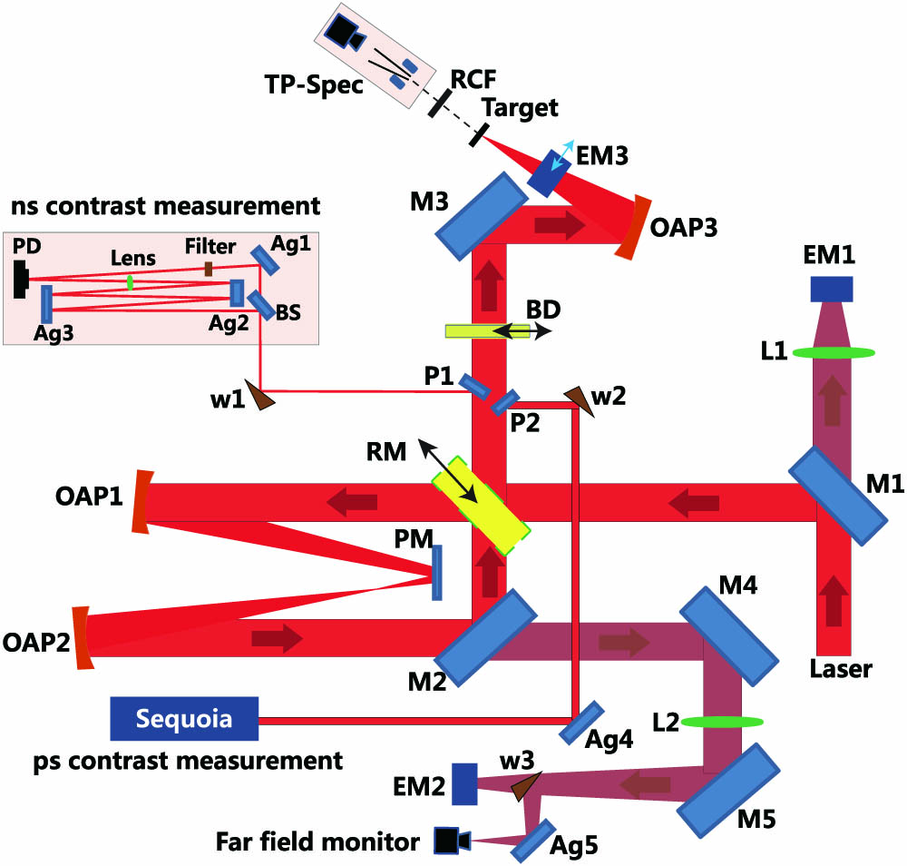
The experiments were carried out using the 200 TW Ti:sapphire laser at Shanghai Jiao Tong University. The schematic of the PM setup with a suite of characterizing diagnostics and its application to proton generation are shown in Fig. 1. In this study, the laser pulse energy is before going through the PM system and the pulse duration is 25 fs at full width at half-maximum (FWHM). An off-axis parabola (OAP1) mirror was used to focus the -polarized beam onto an antireflective-coated polished fused silica glass (PM) at an incident angle of 10°. The PM preionization reflectivity is less than 0.5%. To ease the alignment, a small part of the mirror was coated with silver to allow higher reflectivity at low incoming laser energy. The intensity on the PM was varied from to by changing the beam size on the surface, so that the prepulses and the ASE below the ionization threshold could be transmitted and hence rejected. After the PM, the specularly reflected divergent beam was recollimated by another identical OAP mirror (OAP2), which was further reflected by a high-reflective dielectric mirror (M2) to the target chamber. A motorized removable high-reflective dielectric mirror (RM) was used to choose whether the PM was employed or not.

Figure 1.Schematic of the experimental setup. Ag1–Ag4 are silver mirrors, W1–W4 for wedged fused silica.
A part of the recollimated main beam, with a diameter of one in out of the 4 in main beam was sampled by two pickup mirrors (P1 and P2) for contrast measurements. A photodiode (PD) and oscilloscope-based ns contrast measurement device and a high-dynamic-range third-order cross correlator (Sequoia, Amplitude Technologies) were used to fully characterize the intensity level of the prepulses and the ASE pedestal simultaneously. For the former one, the sampled beam was further split by a beam splitter (BS). The transmitted arm was heavily attenuated while the reflected arm was focused and delayed for 30 ns. Both beams were then overlapped and detected with a PD. The rising time of the PD is 1 ns and the bandwidth of the oscilloscope is 500 MHz. The relative energy of the laser in the two arms was measured by inserting calibrated filters into the reflected arm. After this calibration, the setup could be employed for single-shot measurement of prepulse contrast. The subnanosecond time scale ASE pedestal profile was obtained by varying the voltage on the photomultiplier detector and by using a set of calibrated neutral-density filters. However, the typical dynamic range for Sequoia was and the measured minimum signal was at the same level as the background in the high contrast case. To increase the dynamic range, a glass was inserted into the beam path to induce a post pulse. The ratio of the ASE intensity to that of the main pulse could then be calibrated by the ratio of the ASE intensity to that of the post pulse. In this way, the dynamic range could be increased to in 300 ps before the main pulse with a time resolution of 20 fs.
The transmitted beam through M2 was focused using an achromatic aspherical lens (L2). A CCD camera was placed in the focal plane of L2 to measure the far-field distribution. The throughput of the PM was measured by recording the leaked beam energies from turning mirrors M1 and M2 using two calorimeters EM1 and EM2. The calorimeter EM3 was used to absolutely calibrate EM1 and EM2. A removable beam dump (BD) was used to prohibit the laser beam from reflecting into the target chamber when characterizing the temporal contrast.
The proton acceleration experiment could be performed by removing the BD. The laser pulse was directed into the target chamber and tightly focused to (FWHM), containing 30% of the laser energy on foil targets under an incident angle of 9° using an OAP3 mirror. The laser peak intensity on the target was . Aluminum and carbon foils of different thicknesses were used as targets. A Thomson parabola spectrometer (TP-Spec) was employed to measure the energy and charge distributions of the ion beam accelerated by the laser pulses with and without the PM. The radiochromatic film (RCF) stack was use to measure the spatial-intensity distribution of the protons.
Nanosecond prepulses and picosecond ASE pedestal contrasts were measured as shown in Figs. 2(a) and 2(b), respectively, for . The contrast ratio was better than from several hundred ns to 6 ns before the main pulse, which quickly increased when approaching the main pulse. Two prepulses at and were measured when no PM was used, which was induced by the scattered lights on the high-reflectance mirror in the main amplifier and could not be simply be removed by the Pockels cell because of an unaffordable large diameter. The peak at is the attenuated main pulse from the reference transmitted arm with an attenuation factor of in comparison to the laser peak at 0 ns. The temporal contrast of the two prepulses is and , respectively. With PM, the two prepulses are significantly reduced to below the noise level (). The peaks at and are artificial due to the scattered laser from the silver mirrors in the measurement device, which was different in time with the prepulses. The initial ASE pedestal contrast is up to 10 ps prior to the main peak, which is improved by 100-fold to after using the PM.
Figure 2.(Color online) (a) Nanosecond laser contrasts before and after using the PM. The peak at is the attenuated main beam from one branch. Another branch of the delayed and focused beam displays that the initial laser pulse has two ultrashort prepulses (in the black curve) at and . The intensity of prepulses is reduced below the noise when using the PM (in the red curve). (b) Picosecond laser contrasts. Two orders of magnitude improvement is measured for 10 ps prior to the main peak.
Four example images and the corresponding lineouts of the far-field distributions of the reflected laser pulses are depicted in Figs. 3(a)–3(d). Figure 3(a) represents the case when the laser footprint was on the Ag-coated area of the PM and laser energy is lower than its ionization threshold, therefore corresponding to an initial laser far field without using the PM. Profiles with a nearly Gaussian distribution were observed.
Figure 3.(Color online) Normalized far-field distribution and lineouts of the reflected pulse, (a) from the Ag-coated surface at low laser energy, avoiding the PM breakdown, (b)–(d) for incoming laser intensities of , , and , respectively. (e) The percentage of encircled energy over the whole beam with respect to the focal spot radius. (f) The integrated reflectivity and Strehl ratio as a function of laser intensity on PM. The error bars are due to shot-to-shot fluctuation and the dashed line represents the Strehl ratio in the case of (a).
The far-field distributions get diffused backgrounds, while retain the concentration, when PM is triggered at an intensity up to . Figures 3(b) and 3(c) correspond to and , respectively. When further increases, the far field will be strongly distorted. Shown in Fig. 3(d) is an example distribution at . The encircled laser energies with respect to the focus radius for the four examples are displayed in Fig. 3(e). It is obvious that the radius, encircled 50% of energy of the reflected beam, is the smallest for the case with low laser energy. We did not measure a better focusability when the PM was triggered. This is contradictory to the results in previous publications where better focusability was measured using the PM[17–19]. The degradation may be due to the phase front distortion by the damaged PM surface, which can be triggered by the several-picosecond rising edge of the main pulse discussed by Rödel et al.[20] or by the prepulses, which were several ps prior to the main pulse, as discussed by Scott et al.[21]. For a wide range of laser intensities on the PM, the far field has no further significant degradation, as shown by the Strehl Ratio in Fig. 3(f).
The reflectivity and the Strehl ratio of the PM with respect to are summarized in Fig. 3(f). An increase in reflectivity from 45% to 80% was measured before the decrease for . By comparison, the Strehl ratio is better than 0.3 for , which gets worse for higher . Therefore, a balance of focusability and reflectivity is expected to achieve the highest peak intensity on the target.
Proton acceleration experiments were performed in two cases, i.e., with and without a PM. The balance between the focusability of the reflected beam and the reflectivity are considered for the best utility of the PM technique. First, we tested the influence of the laser temporal contrast on proton accelerations. The proton spatial-intensity distributions from low contrast (LC) and high contrast (HC) laser irradiations were recorded by RCF, as shown in Figs. 4(a) and 4(b), respectively. The divergence angle was significantly reduced in the HC case[22]. Figure 4(c) shows the dependence of the maximum proton energy on target thickness at a fixed , [, the small variation region in the Strehl ratio and reflectivity in Fig. 3(f)]. For LC lasers when the PM is not employed, the optimal target thickness is , which corresponds to the highest maximum proton energy of 3.3 MeV. This may be due to the prepulse-induced plasma formation at the rear surface[3]. When the PM is employed, the optimal target thickness is significantly decreased, to . The maximum proton energy is increased accordingly by more than two-fold, to 8.6 MeV. In a second experiment, we checked how sensitive the maximum proton energy is to . In this experiment, the targets were fixed as -thick Al foils. As shown in Fig. 4(d), the maximum proton energy increases gradually with increasing up to . The saturation at higher intensities is consistent with the slow variations of both the focusability and reflectivity shown in Fig. 3(f). These test results suggest that the PM is a very robust tool for laser contrast improvement that could be used to enhance the proton acceleration even when significant distortion occurs in far field.
Figure 4.(Color online) Proton acceleration results from testing the performances of the PM setup. (a) The proton beam spatial-intensity distribution for LC and (b) for HC. (c) The dependence of the maximum proton energies on target thicknesses for aluminium foils in LC (black squares) and carbon foils in HC (red circles) at . (d) Maximum proton energy with respect to the laser intensity on the PM surface. The error bars are all due to shot-to-shot fluctuation.
In conclusion, we set up and characterized a PM system into our laser chain that has two ultrashort prepulses at tens of ns ahead the main pulse. The performance of the PM system is checked with proton acceleration experiments. The results show that the PM is a robust and efficient tool for proton acceleration, and can be applied to other research topics of laser-plasma interactions requiring HC laser pulses, such as high harmonic generation from solid surfaces[23].
References
[1] S.-W. Bahk, P. Rousseau, T. A. Planchon, V. Chvykov, G. Kalintchenko, A. Maksimchuk, G. A. Mourou, V. Yanovsky. Opt. Lett., 29, 2837(2004).
[2] G. A. Mourou, T. Tajima, S. V. Bulanov. Rev. Mod. Phys., 78, 309(2006).
[3] M. Kaluza, J. Schreiber, M. I. K. Santala, G. D. Tsakiris, K. Eidmann, J. Meyer-ter-Vehn, K. J. Witte. Phys. Rev. Lett., 93, 045003(2004).
[4] P. McKenna, F. Lindau, O. Lundh, D. Neely, A. Persson, C. G. Wahlström. Philos. Trans. R. Soc. A, 364, 711(2006).
[5] L. M. Chen, F. Liu, W. M. Wang, M. Kando, J. Y. Mao, L. Zhang, J. L. Ma, Y. T. Li, S. V. Bulanov, T. Tajima, Y. Kato, Z. M. Sheng, Z. Y. Wei, J. Zhang. Phys. Rev. Lett., 104, 215004(2010).
[6] M. Nantel, J. Itatani, A.C. Tien, J. Faure, D. Kaplan, M. Bouvier, T. Buma, P. V. Rompay, J. Nees, P. P. Pronko, D Umstadter, G. A. Mourou. IEEE J. Sel. Top. Quantum Electron., 4, 449(1998).
[7] R. J. Gray, D. C. Carroll, X. H. Yuan, C. M. Brenner, M. Burza, M. Coury, K. L. Lancaster, X. X. Lin, Y. T. Li, D. Neely, M. N. Quinn, O. Tresca, C.-G. Wahlström, P. McKenna. New. J. Phys., 16, 113075(2014).
[8] F. Lindau, O. Lundh, A. Persson, P. McKenna, K. Osvay, D. Batani, C.-G. Wahlström. Phys. Rev. Lett., 95, 175002(2005).
[9] H. Daido, M. Nishiuchi, A. S. Pirozhkov. Rep. Prog. Phys., 75, 056401(2012).
[10] A. Macchi, M. Borghesi, M. Passoni. Rev. Mod. Phys., 85, 751(2013).
[11] U. Teubner, P. Gibbon. Rev. Mod. Phys., 81, 445(2009).
[12] A. Yogo, K. Kondo, M. Mori, H. Kiriyama, K. Ogura, T. Shimomura, N. Inoue, Y. Fukuda, H. Sakaki, S. Jinno, M. Kanasaki, P. R. Bolton. Opt. Express, 22, 2060(2014).
[13] A. Jullien, O. Albert, F. Burgy, G. Hamoniaux, J.-P. Rousseau, J.-P. Chambaret, F. Auge-Rocherau, G. Cheriaux, J. Etchepare, N. Minkovski, S. M. Saltiel. Opt. Lett., 30, 920(2005).
[14] H. C. Kapteyn, M. Murnane, A. Szoke, R. W. Falcone. Opt. Lett., 16, 490(1991).
[15] H. Kiriyama, M. Mori, Y. Nakai, T. Shimomura, M. Tanoue, A. Akutsu, H. Okada, T. Motomura, S. Kondo, S. Kanazawa, A. Sagisaka, J. Ma, I. Daito, H. Kotaki, H. Daido, S. Bulanov, T. Kimura, T. Tajima. Opt. Commun., 282, 625(2009).
[16] B. Dromey, S. Kar, M. Zepf, P. Foster. Rev. Sci. Instrum., 75, 645(2004).
[17] G. Doumy, F. Quéré, O. Gobert, M. Perdrix, P. Martin, P. Audebert, J. C. Gauthier, J.-P. Geindre, T. Wittmann. Phys. Rev. E, 69, 026402(2004).
[18] Y. Nomura, L. Veisz, K. Schmid, T. Wittmann, J. Wild, F. Krausz. New J. Phys., 9, 9(2007).
[19] R. Hörlein, B. Dromey, D. Adams, Y. Nomura, S. Kar, K. Markey, P. Foster, D. Neely, F. Krausz, G. D. Tsakiris, M. Zepf. New J. Phys., 10, 083002(2008).
[20] C. Rödel, M. Heyer, M. Behmke, M. Kübel, O. Jäckel, W. Ziegler, D. Ehrt, M. C. Kaluza, G. G. Paulus. Appl. Phys. B., 103, 295(2011).
[21] G. G. Scott, V. Bagnoud, C. Brabetz, R. J. Clarke, J. S. Green, R. I. Heathcote, H. W. Powell, B. Zielbauer, T. D. Arber, P. McKenna, D. Neely. New. J. Phys., 17, 033027(2015).
[22] Y. Fang, X. L. Ge, S. Yang, W. Q. Wei, T. P. Yu, F. Liu, M. Chen, J. Q. Liu, X. H. Yuan, Z. M. Sheng, J. Zhang. Plasma Phys. Controlled Fusion, 58, 075010(2016).
[23] J. Gao, F. Liu, X. Ge, Y. Deng, G. Zhang, Y. Fang, W. Wei, S. Yang, X. Yuan, M. Chen, Z. Sheng, J. Zhang. Chin. Opt. Lett., 15, 081902(2017).