• Acta Photonica Sinica
  • Vol. 52, Issue 2, 0213001 (2023)
Wanle PAN1, Heming CHEN2,*, and Yuchen HU1
Author Affiliations
  • 1College of Electronic and Optical Engineering,Nanjing University of Posts and Telecommunications,Nanjing 210023,China
  • 2Bell Honors School,Nanjing University of Posts and Telecommunications,Nanjing 210023,China
  • show less
    DOI: 10.3788/gzxb20235202.0213001 Cite this Article
    Wanle PAN, Heming CHEN, Yuchen HU. Three-channel Integrated Device for Graphene Electro-optic Modulation and Mode Division Multiplexing[J]. Acta Photonica Sinica, 2023, 52(2): 0213001 Copy Citation Text show less
    Theoretical model of electro-optic modulator
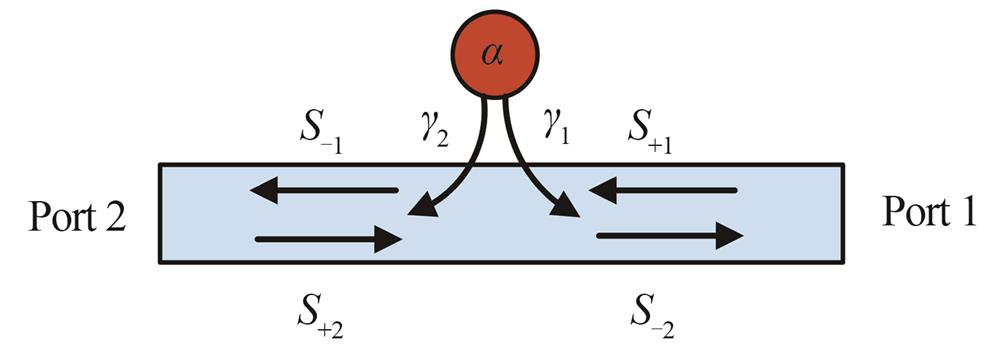
    Fig. 1. Theoretical model of electro-optic modulator
    Transmission spectrum of the theoretical model
    Fig. 2. Transmission spectrum of the theoretical model
    Working principle of electro-optic modulation and MDM integrated device
    Fig. 3. Working principle of electro-optic modulation and MDM integrated device
    Three-dimensional schematic diagram of electro-optic modulation and MDM integrated device
    Fig. 4. Three-dimensional schematic diagram of electro-optic modulation and MDM integrated device
    Structural diagrams of electro-optic modulator
    Fig. 5. Structural diagrams of electro-optic modulator
    The change in effective index and transmission spectrum
    Fig. 6. The change in effective index and transmission spectrum
    3 dB bandwidth of the modulator
    Fig. 7. 3 dB bandwidth of the modulator
    Insertion loss and ∆λ versus the radii of the holes
    Fig. 8. Insertion loss and ∆λ versus the radii of the holes
    Three-dimensional schematic diagram and effective index
    Fig. 9. Three-dimensional schematic diagram and effective index
    Transmission spectrum incident from different ports
    Fig. 10. Transmission spectrum incident from different ports
    Insertion loss and crosstalk versus the widths of the multi-mode waveguides
    Fig. 11. Insertion loss and crosstalk versus the widths of the multi-mode waveguides
    Transmission spectrum of the integrated device
    Fig. 12. Transmission spectrum of the integrated device
    System response time of the integrated device
    Fig. 13. System response time of the integrated device
    Field distribution of the integrated device
    Fig. 14. Field distribution of the integrated device
    ModeExtinction Ratio/dBInsertion Loss/dBCrosstalk/dB
    O1O2O3
    TE028.80.12--45.4-54.7
    TE129.30.20-28.6--46.5
    TE228.30.21-48.4-48.5-
    Table 1. Performance parameters of the integrated device
    Ref.ER/dBIL/dBCT/dB3 dB/GHzVoltage/VMS/GbpsE/(pJ·bit-1
    3>19.3<1.7-18.16-16
    4221.3-715--
    537--0.851.11-23.6
    729--421.6-1.55
    1720<2.1<-19.7-2.5--
    18->10<-23.1-234-
    19>36.5<4.1<-30-2(3)26(72)-
    2719.73<0.46<-14.66-1.24--
    This work>28.3<0.21<-28.61003.8440.25
    Table 2. Comparison of reported devices
    Wanle PAN, Heming CHEN, Yuchen HU. Three-channel Integrated Device for Graphene Electro-optic Modulation and Mode Division Multiplexing[J]. Acta Photonica Sinica, 2023, 52(2): 0213001
    Download Citation