
Kewei Liu, Zihao Wang, Shunyu Yao, Yanan Guo, Jianchang Yan, Junxi Wang, Changxi Yang, Chengying Bao. Mitigating fast thermal instability by engineered laser sweep in AlN soliton microcomb generation[J]. Photonics Research, 2023, 11(8): A10
- Photonics Research
- Vol. 11, Issue 8, A10 (2023)
Abstract
1. INTRODUCTION
Coherently pumped dissipative solitons generated in high- microcavities constitute a major advance in integrated nonlinear photonics and frequency comb techniques in the last decade [1–4]. These miniaturized microcombs can revolutionize many applications including time/frequency metrology [5,6], data transmission [7,8], and spectroscopy [9,10]. However, generating solitons in microcavities still remains a technical challenge, and thermal relaxation induced transient instability is one of the main challenges [1,11–13]. The abrupt intracavity power reduction in soliton formation can cause resonance shifts, pushing the pump frequency detuning outside the soliton existence range (SER). The instability can be avoided by using the self-injection-locking (SIL) approach for soliton generation [14–18]. Considering the available pump power from diode lasers, SIL generally requires a relatively high -factor, especially for microwave rate solitons. Laser cavity soliton microcombs, generated within a microresonantor embedded in an active fiber cavity, are also robust against thermal instability, but the comb bandwidth may be limited by the active Er-gain bandwidth [19]. Reducing thermal absorption of microcavities is another option to overcome thermal instability; thus, soliton generation can become possible by simply tuning the pump from blue to red slowly (even manually) [12,13]. For microcavities with relatively strong thermal effects, experimental approaches including power kick [11,20], active capture [21], dual-pump [22,23], and fast laser frequency sweep [24,25] have been demonstrated to mitigate thermal instability for soliton generation. Typically, power kick needs complicated pump power tuning protocols, while dual-pump needs an additional auxiliary laser. As a variant of the dual-pump method, the auxiliary pump in the dual-pump can be generated by electro-optically modulated sidebands [26,27]. Although it avoids an additional laser, a higher overall pump power is needed. Another variant is generating the Brillouin–Kerr soliton by a blue-detuned pump, but it requires the cavity modes arranged appropriately and the cavity material exhibiting strong Brillouin scattering to realize red-detuned Brillouin lasing for soliton generation [28]. Pumping a resonance with a closely spaced neighbor mode, so that the pump can be coupled into the cavity via the other mode, is another feasible way to mitigate thermal instability, but it works only for some specific modes [29].
Fast laser frequency sweeping can be a relatively efficient and simple way for high-fidelity soliton generation. Generally, the thermal effect is relatively slow, and instability can be suppressed by fast laser sweeps. A fast sweep can be implemented by a single-sideband modulator (SSBM), which can be integrated using the thin-film lithium niobate platform [30], driven by a voltage controlled oscillator (VCO) [24]. The laser scan time usually needs to be faster than the thermal relaxation time to reduce heat accumulation. For silicon nitride (SiN) microcavities with a several-million -factor, scanning speed of about 10s GHz/µs is typically needed [25,31]. For on-chip crystalline cavities, e.g., AlN microcavities, which have faster thermal relaxation, scanning speeds need to be as high as 100s GHz/µs [32,33]. If the scanning speed is not high enough, another power-kick step would be needed to generate AlN soliton microcombs [34]. The ultrahigh laser scan speed requires VCO with a large voltage-to-frequency slope and a large bandwidth function generator. VCO with a large slope means that the voltage fluctuations will convert into pump frequency noise stronger, while function generators with a large bandwidth will increase the system cost and are hard to integrate. Hence, it is important to investigate soliton generation with not very fast laser tuning.
In this paper, we demonstrate soliton generation in an AlN-on-sapphire microcavity with a laser scan speed lower than 30 GHz/µs, which is attainable for distributed Bragg reflector (DBR) lasers by direct current tuning [25]. By engineering the laser sweeping waveform (adding backward plus forward tuning or a two-step backward tuning after the first fast forward tuning), thermal recoil [25] and instability can be mitigated for soliton generation. Our numerical simulation based on a generalized Lugiato–Lefever equation (LLE) [12,13,35,36] shows the importance of two relaxation processes in understanding the soliton generation dynamics. Different from previously studied soliton generation using slow laser tuning where a larger soliton number is favored to balance thermal effects [12,13], a small soliton number can reduce the thermal effects when using fast laser tuning. Our work is important to tailor soliton dynamics in microresonators with fast thermal relaxation.
Sign up for Photonics Research TOC. Get the latest issue of Photonics Research delivered right to you!Sign up now
2. RESULTS
A. Experimental Setup and AlN Microcavity Thermal Properties
The AlN microcavity was fabricated from metal-organic chemical vapor deposition (MOCVD) AlN crystalline film deposited on a sapphire substrate. The same microcavity design as in our previous work was used [37,38]. The microcavity has a radius of 100 μm and a free spectral range (FSR) of about 227 GHz. For dissipative Kerr soliton generation, we pumped the mode around 1547.9 nm, which exhibits an anomalous dispersion (group velocity dispersion ). The loaded -factor and intrinsic -factor of this pumped mode are 1.0 million and 1.4 million, respectively. This supports an on-resonance cavity enhancement ratio of up to 226. Figure 1(a) shows the setup of the SSBM-based fast laser sweep for soliton generation. The SSBM was driven by a VCO, which converts the time-varying waveform from an arbitrary function generator (AFG) to microwave signals with sweeping instantaneous frequency. The modulated pump laser was split by a 90/10 coupler; one was used to monitor the pump frequency sweep by a Mach–Zehnder interferometer (MZI) with an FSR of , while the other seeded an Er-doped fiber amplifier (EDFA) to pump the microcavity. The transmitted pump was suppressed by a fiber Bragg grating (FBG) so as to monitor the comb power change.
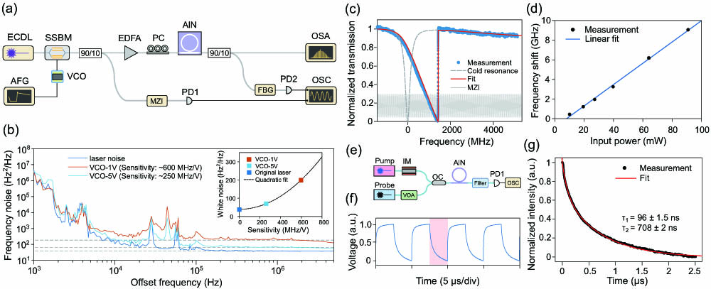
Figure 1.Fast laser sweep system and thermal characterization of the AlN microcavity. (a) Schematic of the experimental setup. ECDL, external cavity diode laser; SSBM, single-sideband modulator; VCO, voltage controlled oscillator; AFG, arbitrary function generator; PC, polarization controller; MZI, Mach–Zehnder interferometer; FBG, fiber Bragg grating; PD, photodiode; OSA, optical spectrum analyzer; OSC, oscilloscope. (b) Measured frequency noise of the carrier-suppression single-sideband signals with different VCO drive voltages and the original laser. The inset shows their white noise, which increases nearly quadratically with the voltage-to-frequency slope of the VCO. (c) Thermal triangle (blue dots) and corresponding fit (red line) of the AlN microcavity with 19.2 mW on-chip pump power. The gray dashed line represents the cold resonance, and the MZI fringes were used to calibrate the frequency axis. (d) Thermal and Kerr induced resonance shift increases nearly linearly with the on-chip pump power. (e) Experimental scheme for the thermal relaxation time measurement of our AlN microcavity. IM, intensity modulator; VOA, variable optical attenuator; OC, optical coupler. (f) Measured probe laser transmission with a 200 kHz square wave applied on the IM. (g) Extracted probe transmission within the shaded box in panel (f). The two-term exponential fit (red line) gives two dominated thermal relaxation times of 96 ns and 708 ns.
In the experiment, the SSBM shifts the pump laser to the st sideband, whose frequency is ( is the laser frequency and is the modulation frequency). An extinction ratio of 18 dB was observed between the st sideband and the carrier. Frequency noise of can add to the noise of the shifted sideband (i.e., actual pump). We measured the frequency noise change induced by the SSBM using the delayed-heterodyne method [38]. Figure 1(b) shows the measured frequency noise of the original laser and the shifted sideband subjected to VCO drive voltages of 1 V and 5 V. The shifted sideband has higher frequency noise than the original laser, especially in the white noise regime [see inset of Fig. 1(b)]. The measured white noise was observed to increase quadratically with the voltage-to-frequency slope of the VCO (this slope is around 1 V and around 5 V; the original laser can be regarded as operating at the zero slope point). This quadratic fit (with the parabola center fixed at zero) suggests that the added frequency noise results from voltage fluctuations of the AFG. Since the st sideband was used, the voltage applied to the VCO should be swept from low values to high values to have swept from blue to red for soliton generation. This naturally ensures the drive voltage is kept at higher values, reducing the frequency noise added to the pump wave.
To design an optimal laser sweep function, we first measured the thermal properties of the AlN-on-sapphire microcavity. The thermal strength was measured by adiabatically sweeping the laser across a resonance from blue to red with different pump powers. Figure 1(c) shows the power transmission under 19.2 mW on-chip pump power. Due to thermal and Kerr effects, the measured resonance exhibits a triangular shape and was redshifted from cold resonance by about 1230 MHz with the frequency axis calibrated by the MZI. The transmission can be fitted by a thermal and Kerr nonlinearity broadened line shape including the Fabry–Perot transmission of the waveguide facets [39]. The transmission was measured under different pump powers, and the fitted resonance shift is plotted in Fig. 1(d). The measured resonance shift shows a good linear relationship with a slope of 108 MHz/mW. The resonance redshift is related to the pump power by , where and are thermal and Kerr nonlinear coefficients, respectively; and is the group velocity in the AlN cavity. The group refractive index was calculated to be 2.07 by the mode simulation, i.e., . Taking an estimated of based on the mode simulation, was deduced to be .
The thermal relaxation time of AlN microcavities has not been measured quantitatively, to our knowledge. Here, we measured this time by a pump–probe approach [40], as illustrated in Fig. 1(e). The pump laser was tuned to the blue side of the pump resonance (), and then its power was modulated by an intensity modulator, driven by a 200 kHz square wave. The heated cavity resonances were actuated to the red and recovered to the blue periodically by the square wave. A probe laser with low power, blue-detuned to the neighbor resonance at , was used to detect the thermal effect induced resonance shift with the pump suppressed by a filter. The measured probe power change is shown in Fig. 1(f). We fitted the decaying tail (red shaded region) by a double-exponential function ; see Fig. 1(g). Here and are thermal constants of the two thermal processes, and and are thermal strengths. The fit gives and , while the relaxation time can be as large as 760 ns and 14 μs for a SiN microcavity [20] (but SiN microcavities fabricated by different groups may have different relaxation time scales [40]). There may be a slow third thermal process occurring on a time scale of hundreds of microseconds that may correspond to the cooling of the entire chip. This slow response was not observed in this measurement, but is supported by the comb generation experiment (see Fig. 2).
![]()
Figure 2.Soliton generation using engineered laser sweep methods. (a) Measured comb power change when using the conventional forward only laser sweep. (b) Schematic of the laser sweep waveforms of method-1 and method-2. (c) Measured comb power change when using method-1. When including the additional stage-ii, the soliton step can be elongated but still annihilated in the end. By adding stage-iii, the solitons can be stabilized. (d) Measured comb power change for method-2. When adding stage-ii, the soliton step can be extended to millisecond scale but cannot be fully stabilized. By adding another backward tuning step, the soliton can be stabilized. (e) Soliton spectra for a two-soliton and a two-FSR soliton crystal states generated by method-1 (upper and middle panels) and a single soliton state generated by method-2 (bottom panel). The dashed lines are
B. Engineered Laser Sweep for Soliton Generation
1. Conventional Laser Tuning
Since microcavities take time to heat up (on the thermal relaxation time scale), the abrupt power drop during soliton formation will not disturb the solitons when initializing solitons within a time scale shorter than . In other words, the abrupt intracavity power change is integrated or averaged to yield the thermal response when scanning the pump fast enough, which helps to stabilize solitons. We define the effective detuning as , where is the laser frequency detuning relative to the cold resonance, and is the thermal resonance shift. needs to be kept in the SER to stabilize solitons.
We first adopted a conventional waveform that includes merely a linear ramp voltage (stage-i) to implement the fast sweep with an on-chip pump power of 400 mW, which is about 13 times that of the parametric oscillation threshold. Thus, the SER was estimated to span about six times the cavity linewidth or 1.2 GHz [41]. Restricted by the bandwidth of our AFG (80 MHz), the minimum time duration of stage-i is about 100 ns, yielding an upper limit of the frequency sweep speed (estimated for a drive voltage of 1 V, and the voltage-to-frequency slope decreases with the drive voltage for the used VCO). The measured comb power change includes a soliton step comprising five solitons [Fig. 2(a)]. This step lasted and was destabilized by the thermal recoil [25]. We believe the thermal recoil is a result of the delayed heating of the cavity and redshift of the resonance due to the second thermal relaxation process, as the soliton step already lasts much longer than . The step is descending, suggesting the effective detuning is decreasing and the resonance is redshifting, in contrast to the resonance blueshift that destroys solitons in slow laser tuning. The redshifted resonance eventually pushes to exit the lower boundary of SER and enter the blue-detuned regime (a power spike arises when crossing the resonance), resulting in the observed thermal recoil. Therefore, a simple forward laser scanning is not sufficient to stabilize AlN solitons.
2. Method-1: Laser Sweep with Added Backward plus Forward Tuning
Since the thermal effect is an accumulating effect, reducing the soliton number and intracavity power can help reduce it. Hence, we added a backward tuning step to reduce the soliton number. A backward laser sweep was also used in Ref. [34] with the purpose to follow the resonance blueshift induced by the fast first relaxation process instead of reducing the soliton number and making the microcavity cooler. By optimizing an exponentially backward scan [stage-ii in method-1 in Fig. 2(b); the duration and frequency shift were chosen as 450 ns and 120 MHz in the experiment, respectively] right after stage-i, a two-soliton step, switched from a five-soliton state, was observed [see upper panel in Fig. 2(c)]. Note that the optimal backward tuning duration and frequency shift would vary slightly with the pump power. With the reduced soliton number, the step became longer and lasted . Nevertheless, thermal recoil still existed in this state, resulting in soliton annihilation.
A possible way to circumvent thermal recoil is to add another forward laser scan at the end of stage-ii; see stage-iii in Fig. 2(b). This prevents the second thermal relaxation process from catching up with the red-detuned pump laser. In experiments, we found that the optimal duration of the additional forward tuning is generally two to three times . By setting the forward tuning duration as 1.5 μs and frequency shift as 900 MHz, the soliton steps can eventually be stabilized [see bottom panel in Fig. 2(c)]. The comb power shown in Fig. 2(c) indicates that the soliton number switched as , and the solitons were stabilized in a two-soliton state. The transition from six-soliton to three-soliton occurred due to backward tuning, as the step was descending. The soliton number switching from should occur due to the mode-interaction induced dispersive wave emission [42] [see the spectrum in Fig. 2(e) and discussion on method-2], as the three-soliton step is increasing. In principle, backward tuning is not necessary or stage-iii can be followed right after stage-i (as suggested in Ref. [25]). However, if the soliton number is large, the forward tuning in stage-iii would require a large frequency shift that may exceed the tuning range of the VCO; therefore, it did not work in our experiments.
The measured spectra of the stabilized two-soliton state are shown in Fig. 2(e). The top panel is a state with solitons spaced by 588 fs, as deduced by the fit with interference (dashed black line). The 3 dB bandwidth of a single soliton spectrum is 9.8 THz, or soliton duration , i.e., a full width at half-maximum (FWHM) pulse width of 32 fs. The spectrum in the middle panel is a two-soliton crystal state with solitons spaced by half of the round trip [43,44]. Some weak lines with about power can be observed in the spectrum, as the soliton spacing may not be perfectly half of the round trip time. Both spectra exhibit dispersive wave emission on the long wavelength side.
3. Method-2: Laser Sweep with Added Two-Step Backward Tuning
As noted above, dispersive waves can also be harnessed to reduce the soliton number [42]. Hence, we increased the end detuning of stage-i to enhance the dispersive wave power and reduce the soliton number [see method-2 in Fig. 2(b)]. Another benefit of increasing the end detuning is that it can make the detuning closer to the upper boundary of the SER so that the thermal recoil induced resonance redshift cannot catch up with the pump.
Different from method-1 where the soliton number switching mainly occurs in the backward tuning in stage-ii, the soliton number has substantially decreased due to dispersive wave emission within stage-i. As a result, the total accumulated heat and resonance induced by the second thermal process are even weaker. In method-2, we also added exponential backward tuning [stage-ii in Fig. 2(b)] after stage-i. Compared to method-1, the backward tuning lasted longer (a duration of about three to five times ), and it is used to chase the resonance blueshift induced by the first thermal process and the fast power drop in soliton formation (note that power drop is larger in method-2 than in method-1 as fewer solitons form in stage-i) so as to prevent soliton annihilation from a too large . When using a waveform including stage-i and stage-ii, the soliton step can be extended to millisecond scale, as shown in the upper panel of Fig. 2(d). Although the achieved soliton duration exceeds the second thermal relaxation time by far, the solitons are still annihilated in the end. However, there is no power spike at the end of the step, suggesting the pump remains red-detuned ( exits the SER from the upper boundary) as opposed to crossing resonance from red-detuned to blue-detuned as in the thermal recoil shown in Figs. 2(a) and 2(c). Hence, we suspect there is a much slower thermal process on the millisecond scale (see the gradually increasing comb power within the step after the laser scan ended), which may arise from the cooling of the entire chip. In addition, the two-soliton step () is longer than the single-soliton step (), because a larger soliton number resists the resonance shift induced by the possible third thermal process better.
To stabilize the soliton, we added the second backward tuning (stage-iii) at the end of the waveform to chase the slow cooling of the chip and resonance blueshift, as shown in Figs. 2(b) and 2(d). By setting the duration to 8 ms and frequency shift to 1.3 GHz for stage-iii, we obtained a stable single-soliton state, whose comb power change is shown in the lower panel of Fig. 2(d). The soliton number decreases from two to one at around 10 µs, as the backward laser tuning in stage-iii exceeds the resonance blueshift induced by the possible chip cooling. The inset shows the observed power oscillation in the soliton number switching, which can be an indication of soliton breathing [45] when is near the lower boundary of the SER. The spectrum of the stabilized single-soliton state is shown in Fig. 2(e) and is associated with a dispersive wave emission around 1670 nm.
4. Repeatability of Soliton Generation
To show the repeatability of our methods, we performed iterative fast frequency sweeps by periodically triggering the AFG every 200 ms. The AFG traces (blue) and the measured comb traces (purple) in 5 s are shown in Fig. 2(f). Successful soliton triggers are highlighted by the shaded boxes. The difference between the middle and bottom panels is the backward tuning frequency amounts in stage-iii, which are 0.9 GHz for Fig. 2(f-ii) and 1.3 GHz for Fig. 2(f-iii). The larger backward tuning slope in stage-iii can result in soliton number switching when it exceeds the resonance blueshift induced by the chip cooling. Hence, these two panels stop in a two-soliton state and a single-soliton state, respectively.
The observed success rate is not very high in the experiment. A possibility for the relatively low rate for method-1 is the soliton number after backward tuning is random. Method-2 has a relatively higher success rate, as the dispersive mediated soliton number limit is relatively deterministic [42]. Another possibility is the poor repeatability of the piezo-module in the laser. Note that we also scanned the laser wavelength by a piezo periodically in this iterative experiment, since a relatively large frequency tuning range was needed to break the obtained comb state and eliminate all the intracavity power. Thus, the AFG induced pump sweep may not start from exactly the same initial in different iteratives. Despite the relatively low success rate, automatic soliton generation can be reached within seconds.
The experiment also enabled measurement of the soliton power change over several milliseconds. For instance, the power of the soliton generated by method-1 increases for milliseconds until reaching an equilibrium state [Fig. 2(g-i)]. This also supports the possible cavity cooling (resonance blueshift) in this time scale. But this resonance blueshift will not cause soliton annihilation, as the is relatively close to the lower boundary of SER in method-1. Due to the second backward tuning in method-2, the resonance blueshift is resisted, and the soliton power is observed to increase and then decrease within the step [Figs. 2(g-ii) and 2(g-iii)]. The used frequency shift and duration in each step in the above examples can be used as a general reference, but fine adjustment is needed for different samples to get optimal results.
3. NUMERICAL SIMULATION
A. Simulation Model
To understand how the engineered laser sweep mitigates thermal instability, we numerically investigated the soliton generation using the generalized LLE augmented by thermal effects as [12,13,35,36]
B. Thermal Mitigation in Simulations
We first simulated the thermal recoil effect in Figs. 3(a)–3(c). We used a conventional forward only scanning (with increasing from to in 100 ns) in the simulation. The corresponding intracavity field evolution is shown in Fig. 3(a). A five-soliton state was generated after the laser sweep ended, but they annihilated at about 750 ns. The resulting changes of intracavity power and are plotted in Fig. 3(b). Due to the delayed thermal accumulation, becomes more negative within the soliton step. Due to decreasing , solitons started to breathe [dashed line in Fig. 3(b)]. Then, exited the lower boundary of the SER, and the pump crossed the effective resonance and became blue-detuned. A power spike and exponential power decay are observed in this process as in experiments. When further analyzing the change of , we found that the second thermal relaxation process contributed to the observed thermal recoil. becomes more negative within hundreds of nanoseconds, which leads to annihilation of the solitons; see the arrow in Fig. 3(c).
![]()
Figure 3.Simulations of soliton generation dynamics with two thermal relaxation processes. (a) Intracavity field dynamics when sweeping the laser in a conventional way. (b) Corresponding changes of intracavity power and effective detuning
To mitigate the thermal recoil, method-1 can be used [see Figs. 3(d)–3(f)]. The laser was first forward tuned from to in 100 ns. Although we used exponential backward and forward tuning in the experiment, the simulations show that linear backward plus forward tuning can also be effective. The soliton generation dynamics is shown in Fig. 3(d). With the added backward tuning, the pulse number decreased to three [Fig. 3(e)]. Thus, is smaller in Fig. 3(f) than in Fig. 3(c). In other words, the backward tuning and reduced soliton number help to mitigate the second thermal relaxation process. However, can still push out of the SER [see red curve around 600 µs in Fig. 3(e)]. The added forward tuning balances the descending [see arrow in Fig. 3(f)]; thus, is pulled back to the SER and the solitons are stabilized. In this process, the enhanced dispersive wave emission causes annihilation for one of the solitons to reach a two-soliton state. As an aside, soliton annihilation in backward tuning is usually associated with breather collision, while there is no such collision in dispersive wave mediated soliton annihilation.
The effectiveness of method-2 is validated in Figs. 3(g)–3(i). In this method, the first forward tuning ended at , a larger than that of method-1. Due to the larger ending , dispersive wave emission is enhanced and reduces the soliton number to two within forward tuning [Figs. 3(g) and 3(h)]. As the soliton number is smaller, a power drop in soliton formation is larger. As a result, becomes less negative upon the formation of solitons. Therefore, the first backward tuning is used to resist the increasing tendency of to prevent increasing from pushing outside the SER from the upper boundary [see arrow in Fig. 3(i); note that is negligible within this fast time scale]. The two-soliton step can be elongated and stabilized by this backward tuning alone in simulations for the two thermal relaxation processes considered in Eq. (2). In experiments, the second backward tuning was used to resist the suspected chip cooling and lasted 8 ms, which is too long for the current simulation capacity. Hence, the second backward tuning was mainly added to mimic the observed soliton number switching from two to one observed during backward tuning in Fig. 2(d); see Figs. 3(g) and 3(h). When the soliton number reduces to one, both and become less negative and push towards the SER [red curve in Figs. 3(g)].
Based on the above simulations, we can summarize that the backward tuning in method-1 was used to reduce the soliton number, and forward tuning balances the decreasing [arrow in Fig. 3(f)]. Soliton number reduction mainly occurs due to dispersive wave emission, and the first backward tuning mainly contributes to balancing increasing [arrow in Fig. 3(i)] in method-2. The choice of method-1 or method-2 depends on the microresonator characteristics. Method-1 works better for microresonators with relatively weak dispersion waves. Since soliton number reduction in backward tuning is random, whether solitons can be stabilized is also random. If there are strong dispersive wave emissions, method-2 may be used and is more deterministic.
C. Requirement on Laser Sweep Speed
A key parameter is the minimum laser sweep speed needed to stabilize soliton microcombs. In general, a lower laser sweep speed relaxes the hardware burden, reduces noise transduction from VCO, and is favored. Here, our analysis assumed a loaded -factor of about 1 million (same parameters as in Sections 3.A and 3.B except that is set as to better induce a two-soliton state), and the needed laser sweep speed can be lower for higher--factor (narrower cavity linewidth) cases. Simulations show that our methods remain effective for microcavities with lower -factors, but the actual laser sweep waveform needs to be optimized.
To investigate the low sweep speed limit, we first simulated the sweep rate needed in stage-i to initiate solitons. We started the linear forward sweep from and stopped at different to see if transient solitons were generated. The minimum and maximum ends that can support a transient two-soliton state under different scan times are shown in Fig. 4(a). After considering thermal effects, needs to be larger than the case without considering thermal effects. The range for to support solitons becomes narrower when sweep times become longer.
![]()
Figure 4.Requirement of laser sweep speed for mitigating thermal instability. (a) Simulated upper and lower limits of laser end detuning versus the stage-i scan time. The shaded region is the SER without considering thermal effects. (b) Minimum laser scan speed for stage-i and backward tuning stage-ii versus the stage-i scan time. The intersect can be regarded as the minimum scan speed. (c) Calculated minimum laser scan speed versus thermal relaxation time with different thermal strengths.
The minimum forward sweep speed required in stage-i can be determined by the minimum end and the corresponding sweep time [green dots in Fig. 4(b)]. After obtaining this sweep speed requirement, we studied the lowest backward tuning speed needed to stabilize the solitons. Since we have assumed to reach a two-soliton state in stage-i, one-step backward tuning is sufficient to stabilize solitons in the simulation [see Section 3.B and Figs. 3(g)–3(i)]. This limit was determined by finding the minimum sweep that can prevent from exiting the SER from the upper boundary in simulations [see inset of Fig. 4(b) for an example]. The needed backward tuning speed increases when the sweep time (speed) for stage-i increases (decreases). Thus, the intersect of these two curves can be regarded as the minimum sweep speed needed. For and used in Section 3.B, the theoretical minimum sweep speed is 5.2 GHz/µs. It is also interesting to note that backward tuning is not needed when the stage-i scan time is 100 ns and scan speed is 30 GHz/µs in Fig. 4(b), while such a speed still needs an engineered sweep in the experiment. A possible reason is that needs to be swept close to the upper boundary of the SER to enable soliton number reduction via dispersive waves in the experiment, and backward tuning is needed to pull towards the SER. In the simulation, we assumed a relatively strong dispersive wave, and is close to the lower boundary of the SER in the analysis; thus, backward tuning is not needed.
This minimum laser sweep speed mainly depends on the first thermal relaxation process, i.e., and . We varied the relaxation time and to obtain the required laser sweep speed in soliton generation as shown in Fig. 4(c). The minimum sweep speed decreases with longer thermal relaxation times and decreasing . The discussion in Fig. 4 focuses on method-2, and the second thermal relaxation process does not impact the soliton generation dynamics much. The used is close to or higher than the measured . For a relaxation time , about 10 GHz/µs is enough to stabilize solitons in simulations, consistent with the experimentally used . The added backward plus forward tuning stages in method-1 would require lower scan rates, as they mitigate the second thermal process much slower than the first thermal process dealt with in method-2.
4. CONCLUSION
We have demonstrated two methods to mitigate the thermal instability in soliton microcomb generation in AlN microresonators. By adding tuning steps after the first fast laser sweep stage, solitons can be stabilized with intermediate sweep speeds. AlN is promising for visible photonics, and the demonstrated methods may be used for visible soliton generation. The engineered laser sweep protocol relaxes the requirement of laser sweep speed; thus, lower bandwidth function generators or even field programmable gate arrays (FPGAs) can be used to drive the SSBM module, which would greatly benefit system miniaturization. It can also reduce the noise transduction from the drive to the pump frequency noise via the VCO. Our experiment and simulation also reveal how thermal relaxation processes occurring on different time scales impact the soliton generation dynamics. Our work focused on soliton generation in microresonators with fast thermal relaxation, and the methods should also work for materials with strong thermal strength such as AlGaAs and Si microresonators.
References
[40] J. Wang, Y. Xuan, A. M. Weiner, M. Qi. Fast and slow optical modulation of refractive index in a SiN microring. CLEO: Science and Innovations, STh1M-8(2014).

Set citation alerts for the article
Please enter your email address
© Copyright 2018-2021 | Chinese Laser Press. All Rights Reserved 沪ICP备15018463号-20