Abstract
We report here on a diode-pumped pulsed mid-infrared laser source based on gas-filled hollow-core fibers (HCFs) towards an all-fiber structure by the tapering method. The pump laser is coupled into an acetylene-filled HCF through a tapered single-mode fiber. By precisely tuning the wavelength of the diode to match different absorption lines of acetylene near 1.5 μm, mid-infrared emission around 3.1–3.2 μm is generated. With 2 m HCFs and 3 mbar acetylene gas, a maximum average power of 130 mW is obtained with a laser slope efficiency of ~24%. This work provides a potential scheme for all-fiber mid-infrared fiber gas lasers.Since the first demonstration of fiber lasers in 1961[1], fiber lasers have developed rapidly and attracted enormous interests, standing out over other laser sources for the advantages of excellent beam quality, high conversion efficiency, long interaction length, and long-term stability. Extending the operation wavelengths of fiber lasers from the near-infrared to mid-infrared region is an active pursuit because the retina-safe wavelengths region contains several high atmospheric transmission windows. It provides a variety of potential applications in defense, security, atmosphere monitoring, and medicine[2]. Additionally, the mid-infrared spectral region coincides with rotational–vibrational transitions of many molecules, and the transition strengths are generally stronger than corresponding transitions, which lie in the near-infrared and visible regions, making mid-infrared sources a natural pump source for longer-wavelength lasers[3]. However, for general silica fibers, the emission wavelengths are limited below due to the maximum phonon energy at room temperature[2]. To obtain lasers beyond , we usually use fibers made of mid-infrared-transparent soft glasses, such as fluoride glasses and chalcogenide glasses[2–6]. However, due to some inevitable restrictions in terms of optical strength, chemical resistance, thermal stability, and so on, mid-infrared fiber lasers based on soft glasses are strongly hindered[2]. As we all know, gases are common gain media for high power mid-infrared lasers, especially for wavelengths unavailable from rare-earth-doped fibers. The development of hollow-core fibers (HCFs) with low loss at the mid-infrared band opened new avenues for mid-infrared fiber lasers by gases[7].
In the past decade, gas-filled HCFs have been intensively used to generate near-infrared and mid-infrared laser emissions based on the stimulated Raman scattering (SRS) effect[8–14] and population inversion[15–20]. However, up to now, all these HCF gas lasers are demonstrated in the structure of spatial light coupling. In the connection, vacuum chambers or gas cells are usually employed, and the pump light is launched into HCFs through windows using standard optical components. Although the coupling efficiency by this approach can be very high, such a system is bulky and cumbersome. In addition, even tiny external perturbations can lead to misalignments, decreasing the pump coupling efficiency, and meanwhile increasing the overlap between the incident pump beam and the HCF’s microstructure, leading to damage at the end of the HCFs. All these will limit the applications of fiber gas lasers. A possible alternative coupling method includes direct fusion splicing of a solid-core single-mode fiber (SMF) to the HCF[21], which is much more stable and compact compared to the free space coupling arrangement. Nevertheless, due to the micro-hole collapse effect and the mode field mismatch between HCFs and SMFs, the coupling loss will be significantly increased, especially for anti-resonance HCFs. Recently, a new kind of technique named a nanospike is reported[22,23], which is fabricated by thermally tapering an SMF down to a diameter of hundreds of nanometers that can be easily inserted into the core of the HCF. This way offers suppression of Fresnel reflection and automatic mode-field diameter matching between the SMF and HCF with very high launch efficiency.
In this Letter, we demonstrate an all-fiber single-pass pulsed mid-infrared fiber gas laser based on gas-filled HCFs by fiber tapering technology. A solid-core SMF, tapered thermally to a tip with the diameter of several tens of micrometers, is inserted into the core of the HCF, then the connection is sealed with epoxy glue, and the HCF is filled with acetylene by a specially designed output gas cell. When the pump is precisely tuned to different absorption lines of acetylene around , stable step-tunable mid-infrared emission in the range of is observed. With 2 m HCFs and 3 mbar (1 mbar = 100 Pa) acetylene gas, a maximum average power of ( single pulse energy) at both P(11) and P(13) pump transitions is obtained, and the laser slope efficiency is .
Sign up for Chinese Optics Letters TOC. Get the latest issue of Chinese Optics Letters delivered right to you!Sign up now
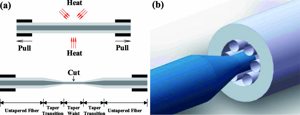
The layout of the tapering process is shown in Fig. 1(a). The two ends of the SMF are fixed by jigs symmetrically and pulled apart at equal and opposite speeds, while the waist in the middle is softened by triangular heat flux distribution sources. The waist diameter of the SMF will be tapered to tens of micrometers, which is less than the hollow-core diameter of the HCF. The untapered fiber is never heated and connected to the taper waist by taper transitions at both ends. Then, by cutting the waist in the middle, we can get two tapered fibers. Then, one of them is coupled into the HCF, as illustrated in Fig. 1(b). The scanning cross-section of the used HCF is shown as the inset in Fig. 2. It can be seen that the HCF is comprised of one ring of six untouched cladding silica tubes, forming a negative-curvature hollow core. It has a core diameter of , an outer diameter of , an average cladding tube diameter of , and a silica wall thickness of . The measured transmission losses in the pump () and the emission () spectral regions are about 0.08 dB/m and 0.13 dB/m, respectively, as shown in the inset in Fig. 2. The length of HCF used in the experiments is 2 m.

Figure 1.(a) Taper formation by heating and stretching an SMF. The light gray section represents the fiber cladding, and the dark gray section represents the fiber core, in which both are not to scale. (b) Schematic diagram of the tapered SMF inserted into the HCF.
Figure 2.Schematic of the experimental setup based on coupling between the tapered solid-core fiber and HCF. AOM, acousto-optical modulator; EDFA, erbium-doped fiber amplifier; PM, power meter; XYZ, manual 3D translation stage; W, uncoated sapphire window; L, plano-convex lens; M, mirror on flipper mount; IBF, infrared bandpass filter. Inserts: the measured transmission loss spectrum (red curve and black curve represent fiber loss from 3000 to 3300 nm and from 1500 to 1600 nm, respectively) and the scanning cross-section of the HCF.
A diagram of the experimental setup is given in Fig. 2. At the input of the HCF, the tapered fiber with Fresnel reflection of 0.7% ( waist diameter, taper waist, and taper transition) is mounted on a manual three-dimensional (3D) translation stage and inserted into the core of the HCF with core diameter using a two-dimensional microscope system. The coupling efficiency is measured to be before packaging. In order to ensure fine air-tightness, the connection is carefully sealed with epoxy glue, but the coupling efficiency reduces to due to the tiny sway during the sealing process. Anyway, the final 40% coupling efficiency is stable and remains unchanged. Much higher coupling efficiency can be obtained by optimizing the tapered fiber and improving the package process in the following work. Shown as the left dashed frame in Fig. 2, the pulsed pump laser with 50 ns pulse duration and 500 kHz repetition rate can be tunable from 1525 to 1565 nm, covering the P branch absorption lines of acetylene. The pump linewidth is measured by a Fabry–Perot interferometer to be less than 300 MHz, which is narrower than the Doppler broadening of the absorption lines ( for , room temperature, central wavelength , ignoring pressure broadening)[17]. A fiber coupler with a splitting ratio of 90:10 is used to monitor the input power. The 90% output of the pump laser is spliced to the tapered fiber, and the 10% output is sent to the power meter. The HCFs can be vacuumed or filled with acetylene through a specially designed small gas cell at the output end. After the strong interaction between the pump light and the gain medium, both the laser light and residual pump light would pass through an uncoated sapphire window on the gas cell and be collimated and focused. Through a mirror on a flipper mount, the mixed light could not only be sent to the power meter after separating the laser output from the residual pump light through the infrared bandpass filter (IBF) ( transmittance only at laser wavelengths), but also delivered to an optical spectrum analyzer (OSA) for detecting output laser spectra.
The spectral content of the laser output is measured, and the results are displayed in Fig. 3(a). It can be seen that for different P branch pump lines, the output spectra contain two strong peaks, which change regularly from 3090 to 3203 nm. Explained by Fig. 3(b), acetylene molecules are excited by pump light from the ground vibrational state to the upper level ( vibrational state), creating an immediate population inversion between the upper level and the vibrational state (the lower laser level), since the thermal population of vibrational state at room temperature is negligible[15,16]. Then, the acetylene molecules can leave the vibrational state through radiation transition to the essentially empty vibrational state. But the relaxation transition from the lower level to the ground level is dipole forbidden and relies on non-radiative transitions mechanisms to depopulate the lower laser level[16]. Lasing occurs according to selection rules (or ) referred to as R branch (P branch) transitions. The R and P branch transitions are usually labeled as and , where is the rotational quantum number of the lower state. Similarly, selection rules also apply to the pumping processes. So, the absorption spectrum also consists of an R branch of shorter wavelengths and a P branch of longer wavelengths, and the corresponding wavelengths are shown in the table in Fig. 3. Due to the emission characteristics of customized erbium-doped fiber amplifier (EDFA), the pump spectrum has stronger amplified spontaneous emission (ASE) background when tuned to shorter wavelength absorption lines. The strong ASE background occupies most of the energy of the pump light, which hinders the absorption of acetylene, leading to poor performance of laser emission. Consequently, Fig. 3(a) only shows partial spectral content of the laser output, which is pumped by some odd P branch pump lines with longer wavelengths. Due to the symmetric requirements of the total multi-particle wave function under exchange of identical nuclei, intensities of the even absorption lines are much weaker, so the corresponding emissions have also not been investigated.
Figure 3.(a) Measured spectrum of the mid-infrared laser from acetylene-filled HCF lasers taken at 3.5 mbar with 2 m length of HCF. displayed in upper right corner represent corresponding odd pump lines. (b) The simplified molecular energy-level diagram of acetylene for 3 μm emissions when pumped at absorption band, and the right table displays the odd P branch absorption lines of acetylene molecules used in experiments and the corresponding measured laser wavelengths using the OSA.
The output mid-infrared laser power with respect to the absorbed pump power is shown in Fig. 4. To measure the output mid-infrared laser power, an IBF is used to block the residual pump light. By measuring the incident pump power and the residual pump power after the gas cell, the total absorbed pump power can be given when the pump light is on resonance with the absorption lines of acetylene. From Fig. 4, we can see that the lasing threshold, defined as the minimum absorbed pump power necessary for observation of the mid-infrared laser, increases quickly with the increasing of the acetylene pressure. That is caused by the shortened life of the laser upper-level energy due to the enhanced collision between acetylene molecules. Beyond the threshold, the laser pulse energy increases nearly linearly with the absorbed pump pulse energy, and the slope efficiency stays stably at , which is nearly independent of the acetylene pressures. Such behavior is similar to the hollow-core optical fiber gas lasers pumped by an optical parametric amplifier[24]. But the laser efficiency closely depending on acetylene pressures is more common[15–20]. We think it is affected by the length of HCFs and the cladding structures leading to different fiber loss. The maximum laser pulse energy of (average power of ) is obtained for both P(11) and P(13) absorption lines.
Figure 4.Measured laser pulse energy with respect to absorbed pump pulse energy for a 2 m long HCF filled with various pressures of acetylene gas when pumped with (a) P(11) and (b) P(13) absorption lines, respectively.
In conclusion, we have reported a diode-pumped all-fiber structure pulsed step-tunable mid-infrared laser source by acetylene-filled HCFs. The pump light is coupled into the HCF through a tapered SMF. By precisely tuning the wavelength of the diode to match different absorption lines of acetylene at the band, pulsed step-tunable mid-infrared emission is generated. With 2 m HCFs and 3 mbar acetylene gas, a maximum average power of ( single pulse energy) is obtained with a laser slope efficiency of . This work provides a potential scheme for all-fiber pulsed mid-infrared lasers.
References
[1] E. Snitzer. Phys. Rev. Lett., 7, 444(1961).
[2] S. D. Jackson. Nat. Photon., 6, 423(2012).
[3] M. Bernier, V. Fortin, M. El-Amraoui, Y. Messaddeq, R. Vallee. Opt. Lett., 39, 2052(2014).
[4] V. Fortin, M. Bernier, S. T. Bah, R. Vallee. Opt. Lett., 40, 2882(2015).
[5] Z. Qin, G. Xie, J. Ma, P. Yuan, L. Qian. Chin. Opt. Lett., 15, 111402(2017).
[6] F. Maes, V. Fortin, S. Poulain, M. Poulain, J. Y. Carree, M. Bernier, R. Vallee. Optica, 5, 761(2018).
[7] F. Yu, J. C. Knight. IEEE J. Sel. Top. Quantum Electron., 22, 146(2015).
[8] F. Benabid, J. C. Knight, G. Antonopoulos, P. St. J. Russel. Science, 298, 399(2002).
[9] Y. Chen, Z. Wang, B. Gu, F. Yu, Q. Liu. Opt. Lett., 41, 5118(2016).
[10] Y. Chen, Z. Wang, Z. Li, W. Huang, X. Xi, Q. Lu. Opt. Express, 25, 20944(2017).
[11] Z. Li, W. Huang, Y. Cui, Z. Wang, W. Wu, 26, 12522(2018).
[12] A. V. Gladyshev, A. F. Kosolapov, M. M. Khudyakov, Y. Yatsenko, A. N. Kolyadin, A. A. Krylov, A. Pryamikov, A. S. Biriukov, M. E. Likhachev, I. A. Bufetov. IEEE J. Sel. Top. Quantum Electron., 24, 0903008(2018).
[13] M. S. Astapovich, A. V. Gladyshev, M. M. Khudyakov, A. F. Kosolapov, M. E. Likhachev, I. A. Bufetov. IEEE Photon. Technol. Lett., 31, 78(2019).
[14] W. Huang, Y. Cui, Z. Li, Z. Zhou, Z. Wang. Chin. Opt. Lett., 17, 071406(2019).
[15] A. M. Jones, A. V. V. Nampoothiri, A. Ratanavis, T. Fiedler, N. V. Wheeler, F. Couny, R. Kadel, F. Benabid, B. R. Washburn, K. L. Corwin, W. Rudolph. Opt. Express, 19, 2309(2011).
[16] A. V. V. Nampoothiri, A. M. Jones, C. Fourcade-Dutin, C. Mao, N. Dadashzadeh, B. Baumgart, Y. Y. Wang, M. Alharbi, T. Bradley, N. Campbell, F. Benabid, B. R. Washburn, K. L. Corwin, W. Rudolph. Opt. Mater. Express, 2, 948(2012).
[17] Z. Wang, W. Belardi, F. Yu, W. J. Wadsworth, J. C. Knight. Opt. Express, 22, 21872(2014).
[18] M. R. A. Hassan, F. Yu, W. J. Wadsworth, J. C. Knight. Optica, 3, 218(2016).
[19] M. Xu, F. Yu, J. Knight. Opt. Lett., 42, 4055(2017).
[20] Z. Zhou, N. Tang, Z. Li, W. Huang, Z. Wang, W. Wu, W. Hua. Opt. Express, 26, 19144(2018).
[21] L. Xiao, M. S. Demokan, W. Jin, Y. Wang, C. Zhao. J. Lightwave Technol., 25, 3563(2007).
[22] S. Xie, R. Pennetta, P. St. J. Russell. Optica, 3, 277(2016).
[23] R. Zeltner, S. Xie, R. Pennetta, P. St. J. Russell. ACS Photon., 4, 378(2017).
[24] N. Dadashzadeh, M. P. Thirugnanasambandam, H. W. K. Weerasinghe, B. Debord, M. Chafer, F. Gerome, F. Benabid, B. R. Washburn, K. L. Corwin. Opt. Express, 25, 13351(2017).