• Photonics Research
  • Vol. 7, Issue 5, 573 (2019)
Jiyang Ma1, Longfu Xiao1, Jiaxin Gu1, Hao Li1, Xinyu Cheng1, Guangqiang He2, Xiaoshun Jiang1、*, and Min Xiao1、3
Author Affiliations
  • 1National Laboratory of Solid State Microstructures, College of Engineering and Applied Sciences and School of Physics, Nanjing University, Nanjing 210093, China
  • 2State Key Laboratory of Advanced Optical Communication Systems and Networks, Department of Electronic Engineering, Shanghai Jiao Tong University, Shanghai 200240, China
  • 3Department of Physics, University of Arkansas, Fayetteville, Arkansas 72701, USA
  • show less
    DOI: 10.1364/PRJ.7.000573 Cite this Article Set citation alerts
    Jiyang Ma, Longfu Xiao, Jiaxin Gu, Hao Li, Xinyu Cheng, Guangqiang He, Xiaoshun Jiang, Min Xiao. Visible Kerr comb generation in a high-Q silica microdisk resonator with a large wedge angle[J]. Photonics Research, 2019, 7(5): 573 Copy Citation Text show less
    SEM images of the large-wedge-angle microdisk resonator used in our experiment. (a), (b) Full-scale view of the microresonator. (c) Close-up of the microresonator to show the detailed characteristics of the large wedge angle.
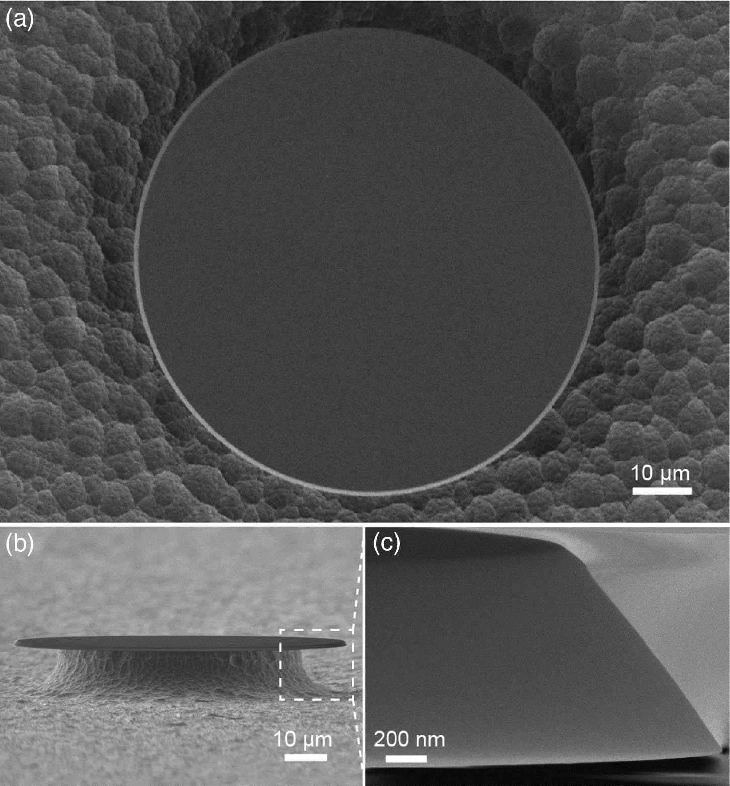
    Fig. 1. SEM images of the large-wedge-angle microdisk resonator used in our experiment. (a), (b) Full-scale view of the microresonator. (c) Close-up of the microresonator to show the detailed characteristics of the large wedge angle.
    (a) Illustration of the mode profile for the fundamental TM10 mode inside the cavity. An indication of angle α shows the definition of the wedge angle. (b) Dispersion characteristics of the TM10, TM20, TM30 modes for the disk 80 μm in diameter, 1 μm in thickness, and a 56° wedge angle. Inset: simulated mode profiles of the TM10, TM20 and TM30 modes, respectively. (c) Variation of the dispersion at the wavelength 780 nm when changing the thickness of the disk at different wedge angles. The diameter is kept at 80 μm, and the used cavity mode for the simulation is the TM10 mode. (d) Variation of the effective index by changing the thickness of the disk for different mode families at the wavelength of 780 nm; during the simulation, the wedge angle and diameter are fixed at 56° and 80 μm, respectively. (e) Variation of the zero dispersion wavelength for the TM10 mode with different wedge angles. The diameter of the microdisk cavity is 80 μm, and the thickness of the microcavity is 1 μm. The red star indicates the angle of the silica microdisk resonator used in the experiment. (f) Dispersion of the TM10 mode for a 56° wedge angle silica disk, 1 μm in thickness and 2 mm in diameter.
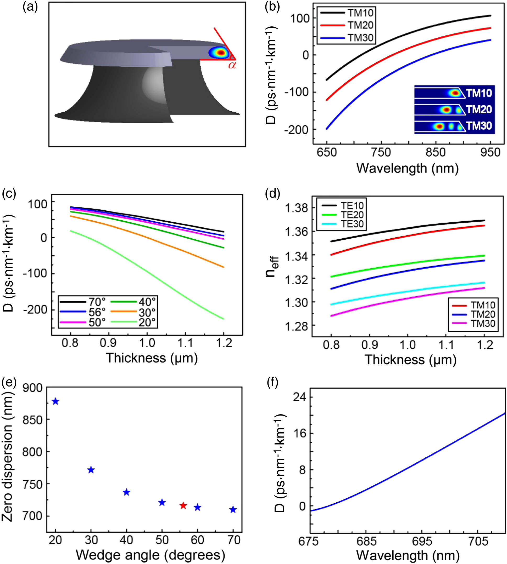
    Fig. 2. (a) Illustration of the mode profile for the fundamental TM10 mode inside the cavity. An indication of angle α shows the definition of the wedge angle. (b) Dispersion characteristics of the TM10, TM20, TM30 modes for the disk 80 μm in diameter, 1 μm in thickness, and a 56° wedge angle. Inset: simulated mode profiles of the TM10, TM20 and TM30 modes, respectively. (c) Variation of the dispersion at the wavelength 780 nm when changing the thickness of the disk at different wedge angles. The diameter is kept at 80 μm, and the used cavity mode for the simulation is the TM10 mode. (d) Variation of the effective index by changing the thickness of the disk for different mode families at the wavelength of 780 nm; during the simulation, the wedge angle and diameter are fixed at 56° and 80 μm, respectively. (e) Variation of the zero dispersion wavelength for the TM10 mode with different wedge angles. The diameter of the microdisk cavity is 80 μm, and the thickness of the microcavity is 1 μm. The red star indicates the angle of the silica microdisk resonator used in the experiment. (f) Dispersion of the TM10 mode for a 56° wedge angle silica disk, 1 μm in thickness and 2 mm in diameter.
    (a) Measured transmission spectrum of the disk used to generate the visible comb; the corresponding intrinsic and loaded Q-factors are 1.08×10⁷ and 0.98×10⁷, respectively. (b) Variation of the side band power with the pump power; the OPO threshold is 1.62 mW. (c) Experimental setup: FPC, fiber polarization controller; PM, power meter; VOA, variable optical attenuator; OSA, optical spectrum analyzer; PD, photo diode.
    Fig. 3. (a) Measured transmission spectrum of the disk used to generate the visible comb; the corresponding intrinsic and loaded Q-factors are 1.08×10⁷ and 0.98×10⁷, respectively. (b) Variation of the side band power with the pump power; the OPO threshold is 1.62 mW. (c) Experimental setup: FPC, fiber polarization controller; PM, power meter; VOA, variable optical attenuator; OSA, optical spectrum analyzer; PD, photo diode.
    Generation of visible Kerr combs with different pump powers. (a) Visible Kerr comb generated with a launched pump power of 21.50 mW. (b) Visible Kerr comb generated with a launched pump power of 28.50 mW. (c) Visible Kerr comb generated with a launched pump power of 36.50 mW.
    Fig. 4. Generation of visible Kerr combs with different pump powers. (a) Visible Kerr comb generated with a launched pump power of 21.50 mW. (b) Visible Kerr comb generated with a launched pump power of 28.50 mW. (c) Visible Kerr comb generated with a launched pump power of 36.50 mW.
    Jiyang Ma, Longfu Xiao, Jiaxin Gu, Hao Li, Xinyu Cheng, Guangqiang He, Xiaoshun Jiang, Min Xiao. Visible Kerr comb generation in a high-Q silica microdisk resonator with a large wedge angle[J]. Photonics Research, 2019, 7(5): 573
    Download Citation