• Photonics Research
  • Vol. 9, Issue 8, 1598 (2021)
Yan Zhou and Minghui Hong*
Author Affiliations
  • Department of Electrical and Computer Engineering, National University of Singapore, Singapore 117576, Singapore
  • show less
    DOI: 10.1364/PRJ.430514 Cite this Article Set citation alerts
    Yan Zhou, Minghui Hong. Formation of a three-dimensional bottle beam via an engineered microsphere[J]. Photonics Research, 2021, 9(8): 1598 Copy Citation Text show less
    Conceptual design of engineered microsphere patterned with the segmented Fresnel annular zones. (a) 3D sketch of optical bottle beam (green) generated from the engineered microsphere. (b) Schematic sketch of the two-segment zone design engineered microsphere, s in the upper inset denotes the total relative dislocation of the opposite segments from the optical axis, while d in the lower inset is the etched depth of the annular zone with an elliptical cross section. (c) Refractive index maps show two embodiments of segmented regions (left: two-segment; right: four-segment), and all total relative dislocation distances are equal to λ. The light scattering by the piecewise interface of a phase FZP and related geometric parameters for (d) ridge zones and (e) groove zones. Sketches in (d) and (e) are not drawn to scale.
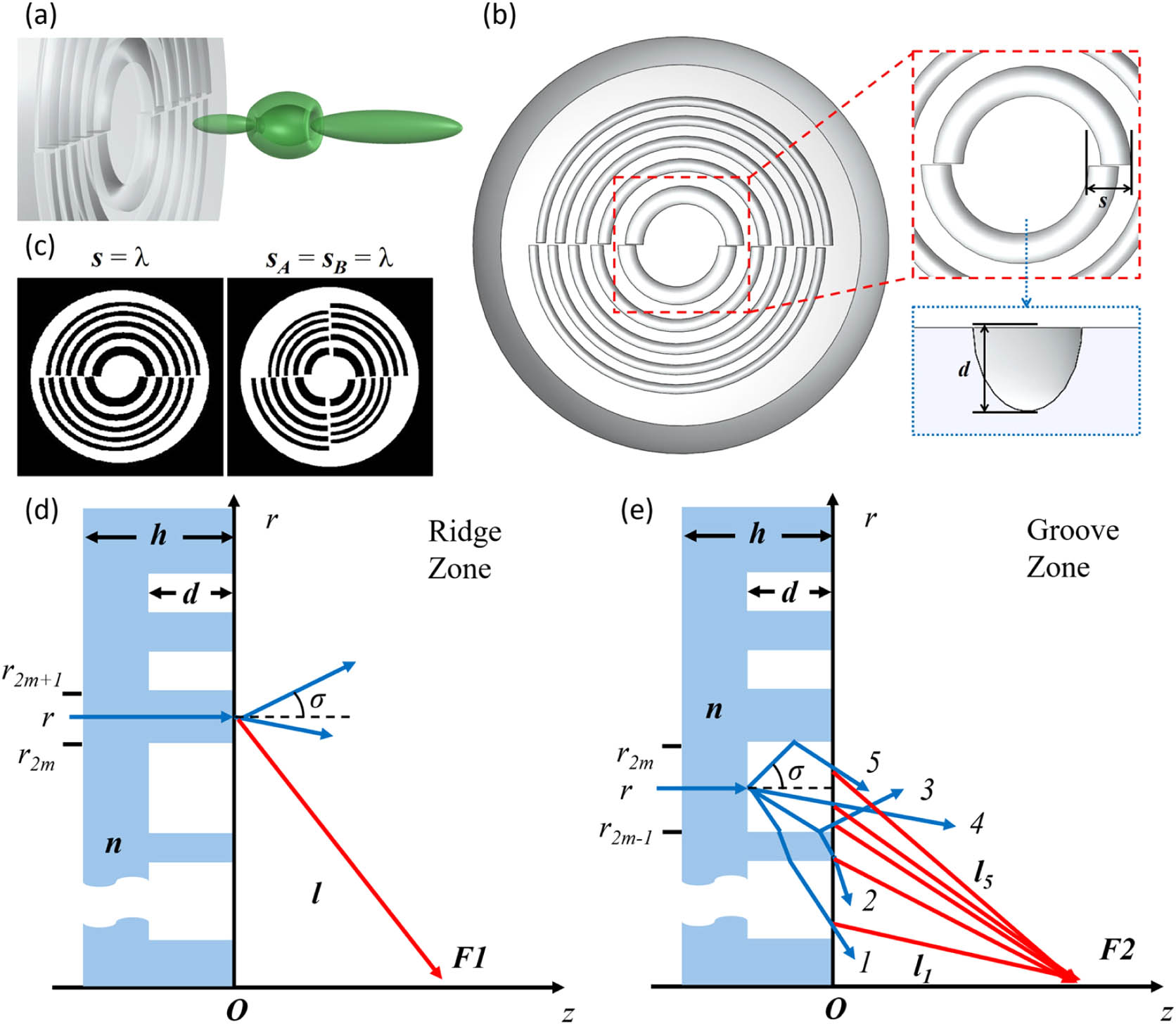
    Fig. 1. Conceptual design of engineered microsphere patterned with the segmented Fresnel annular zones. (a) 3D sketch of optical bottle beam (green) generated from the engineered microsphere. (b) Schematic sketch of the two-segment zone design engineered microsphere, s in the upper inset denotes the total relative dislocation of the opposite segments from the optical axis, while d in the lower inset is the etched depth of the annular zone with an elliptical cross section. (c) Refractive index maps show two embodiments of segmented regions (left: two-segment; right: four-segment), and all total relative dislocation distances are equal to λ. The light scattering by the piecewise interface of a phase FZP and related geometric parameters for (d) ridge zones and (e) groove zones. Sketches in (d) and (e) are not drawn to scale.
    “Bottle beam” generation via a two-segment design engineered microsphere from the view of Poynting vector distributions. (a) A zoomed view of the 3D optical trap with estimated axial and transverse dimensions, which are taken from the square and enclosed region in (b) XZ plane Poynting vector distribution. (c) YZ plane Poynting vector distribution. (d)–(f) The 3D Poynting vector plots taken from the three planes indicated in (b) and (c), where (e) is the optical trap or 3D void and (d) and (f) are the two foci.
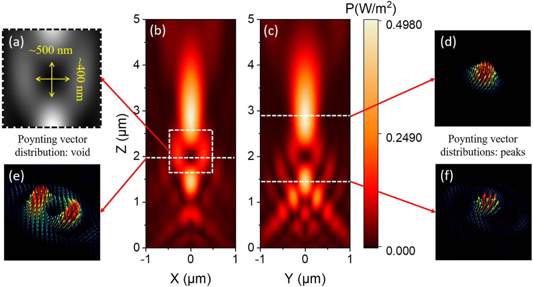
    Fig. 2. “Bottle beam” generation via a two-segment design engineered microsphere from the view of Poynting vector distributions. (a) A zoomed view of the 3D optical trap with estimated axial and transverse dimensions, which are taken from the square and enclosed region in (b) XZ plane Poynting vector distribution. (c) YZ plane Poynting vector distribution. (d)–(f) The 3D Poynting vector plots taken from the three planes indicated in (b) and (c), where (e) is the optical trap or 3D void and (d) and (f) are the two foci.
    “Bottle beam” generation via a four-segment design engineered microsphere from the view of Poynting vector distributions. (a) A zoomed view of the 3D optical trap with estimated axial and transverse dimensions, which are taken from the square and enclosed region in (b) XZ plane Poynting vector distribution. (c) YZ plane Poynting vector distribution. (d)–(f) The 3D Poynting vector plots taken from the three planes indicated in (b) and (c), where (e) is the optical trap or 3D void and (d) and (f) are the two foci.
    Fig. 3. “Bottle beam” generation via a four-segment design engineered microsphere from the view of Poynting vector distributions. (a) A zoomed view of the 3D optical trap with estimated axial and transverse dimensions, which are taken from the square and enclosed region in (b) XZ plane Poynting vector distribution. (c) YZ plane Poynting vector distribution. (d)–(f) The 3D Poynting vector plots taken from the three planes indicated in (b) and (c), where (e) is the optical trap or 3D void and (d) and (f) are the two foci.
    Phase mapping for the designs at the same observation XY plane where the 3D void occurs, both cases are set at a 4λ distance from the exit surface. Upper row: x, y, and z phase distributions for the two-segment design; lower row: x, y, and z phase distributions for the four-segment design.
    Fig. 4. Phase mapping for the designs at the same observation XY plane where the 3D void occurs, both cases are set at a 4λ distance from the exit surface. Upper row: x, y, and z phase distributions for the two-segment design; lower row: x, y, and z phase distributions for the four-segment design.
    Characterization of the fabricated two-segment design microsphere. Images of the fabricated microsphere are taken with (a) SEM and (d) optical microscope. Normalized FDTD-simulated light intensity field |E|2 is plotted in (b) XY and (e) XZ planes, respectively. Measured light intensity fields are presented in (c) XY plane and (f) XZ plane. Scale bars: (a) and (d) 5 μm; (c), (e), and (f) 1 μm.
    Fig. 5. Characterization of the fabricated two-segment design microsphere. Images of the fabricated microsphere are taken with (a) SEM and (d) optical microscope. Normalized FDTD-simulated light intensity field |E|2 is plotted in (b) XY and (e) XZ planes, respectively. Measured light intensity fields are presented in (c) XY plane and (f) XZ plane. Scale bars: (a) and (d) 5 μm; (c), (e), and (f) 1 μm.
    Characterization of the fabricated four-segment design microsphere. Images of the fabricated microsphere are taken with (a) SEM and (d) optical microscope. Normalized FDTD-simulated light intensity field |E|2 is plotted in (b) XY and (e) XZ planes, respectively. Measured light intensity fields are presented in the (c) XY plane and (f) XZ plane. Scale bars: (a) 2 μm; (d) 5 μm; (c), (e), and (f) 1 μm.
    Fig. 6. Characterization of the fabricated four-segment design microsphere. Images of the fabricated microsphere are taken with (a) SEM and (d) optical microscope. Normalized FDTD-simulated light intensity field |E|2 is plotted in (b) XY and (e) XZ planes, respectively. Measured light intensity fields are presented in the (c) XY plane and (f) XZ plane. Scale bars: (a) 2 μm; (d) 5 μm; (c), (e), and (f) 1 μm.
    Yan Zhou, Minghui Hong. Formation of a three-dimensional bottle beam via an engineered microsphere[J]. Photonics Research, 2021, 9(8): 1598
    Download Citation