• High Power Laser Science and Engineering
  • Vol. 3, Issue 1, 010000e8 (2015)
C. Spindloe1、*, D. Wyatt1, D. Haddock1, I. East1, J. E. Cross2, C. N. Danson2、3, E. Falize4, J. M. Foster2、3、5, M. Koenig6, and and G. Gregori2
Author Affiliations
  • 1Target Fabrication Group, Central Laser Facility, Rutherford Appleton Laboratory, Harwell Science and Innovation Campus, Didcot OX11 0QX, UK
  • 2Atomic and Laser Physics, Clarendon Laboratory, University of Oxford, OX1 3PU, UK
  • 3AWE, Aldermaston, Reading RG7 4PR, UK
  • 4CEA-DAM-DIF, F-91297 Arpajon, France
  • 53
  • 6Laboratoire pour l’Utilisation Des Laser Intense, UMR 7605 CNRS-CEA-Ecole Polytechnique-Universit′e Paris VI, Palaiseau, France
  • show less
    DOI: 10.1017/hpl.2015.2 Cite this Article Set citation alerts
    C. Spindloe, D. Wyatt, D. Haddock, I. East, J. E. Cross, C. N. Danson, E. Falize, J. M. Foster, M. Koenig, and G. Gregori. Target fabrication for the POLAR experiment on the Orion laser facility[J]. High Power Laser Science and Engineering, 2015, 3(1): 010000e8 Copy Citation Text show less
    Experimental layout for the Orion POLAR campaign.
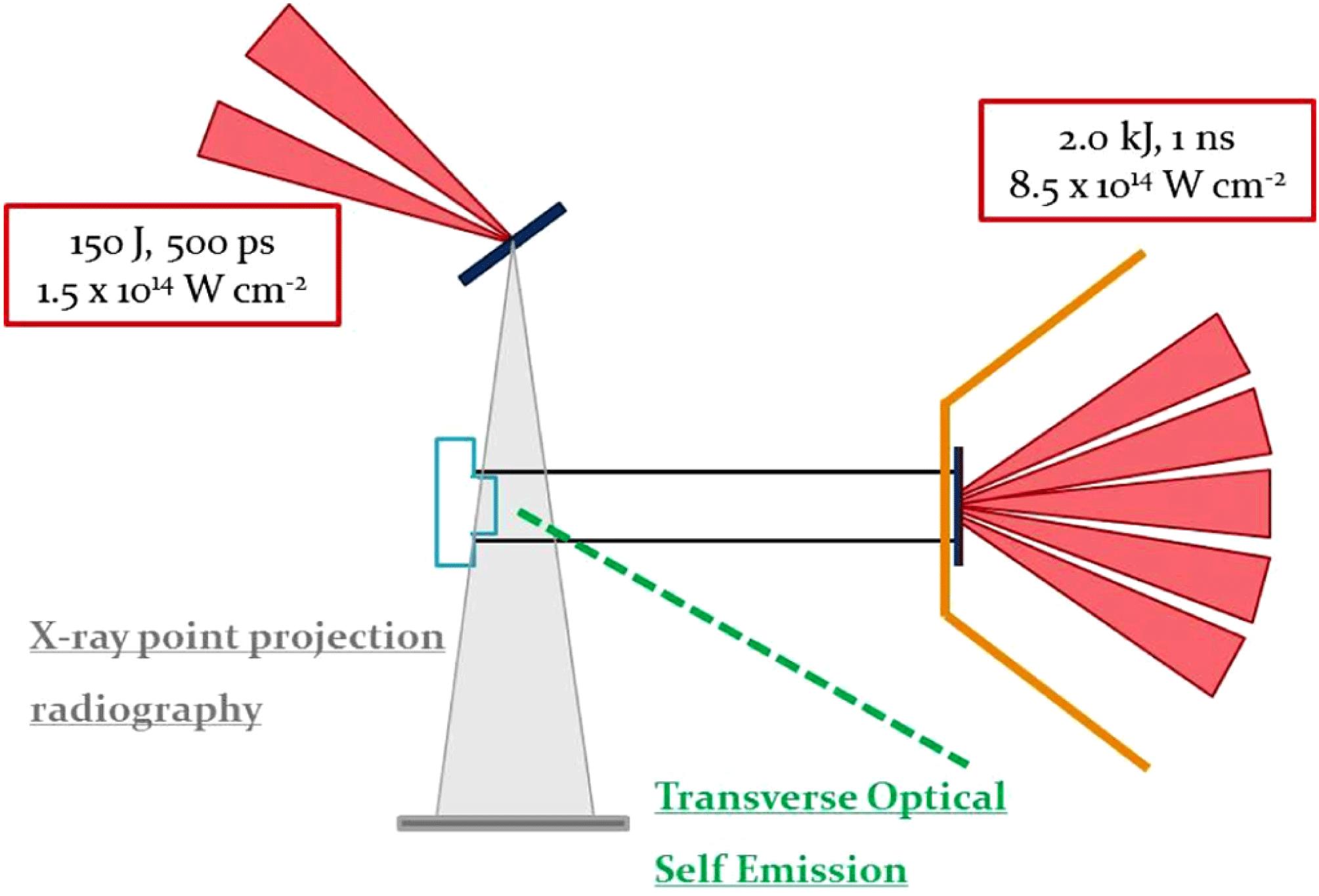
    Fig. 1. Experimental layout for the Orion POLAR campaign.
    A CAD representation of the target sliced through the centreline (annotations are described in the text above).
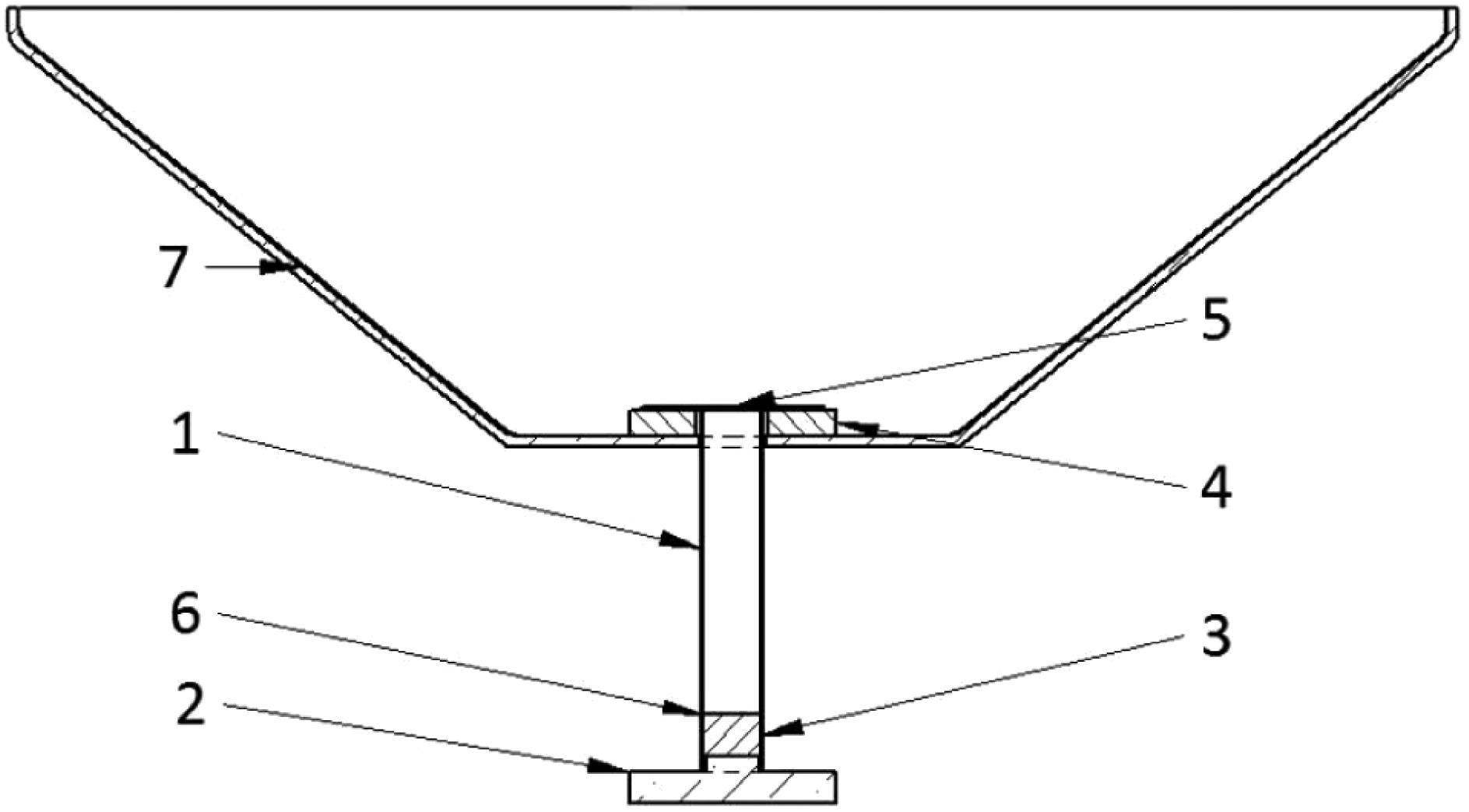
    Fig. 2. A CAD representation of the target sliced through the centreline (annotations are described in the text above).
    Shows a 3D CAD cut away of the target and indicates the positions of the pusher foil position and also shows the foam insert at the bottom of the tube.
    Fig. 3. Shows a 3D CAD cut away of the target and indicates the positions of the pusher foil position and also shows the foam insert at the bottom of the tube.
    A fully processed Brominated plastic disk showing internal structure (dark areas are the un-melted material).
    Fig. 4. A fully processed Brominated plastic disk showing internal structure (dark areas are the un-melted material).
    A low-density sample placed at the end of the PI tube next to the quartz obstacle.
    Fig. 5. A low-density sample placed at the end of the PI tube next to the quartz obstacle.
    Images of the POLAR target from the obstacle side (left) the Au/CH pusher (right).
    Fig. 6. Images of the POLAR target from the obstacle side (left) the Au/CH pusher (right).
    A side view of the foam inside the tube with the grid above.
    Fig. 7. A side view of the foam inside the tube with the grid above.
    The backlighter target design.
    Fig. 8. The backlighter target design.
    The fully assembled backlighter target.
    Fig. 9. The fully assembled backlighter target.
    Sample backlighter images showing: (a) the PI tube with the quartz/steel obstacle at the top, the diagnostic slits cut in to the tube and the gold resolution grid attached to the target and (b) the PI tube with the quartz/steel obstacle at the top and a low-density foam insert below the stop.
    Fig. 10. Sample backlighter images showing: (a) the PI tube with the quartz/steel obstacle at the top, the diagnostic slits cut in to the tube and the gold resolution grid attached to the target and (b) the PI tube with the quartz/steel obstacle at the top and a low-density foam insert below the stop.
    Drive beamsBL beamsBL beams pulseDelay betweenFilters onFilters on
    ImageMain target typetotal energy (kJ)total energy (J)length (ns)cones (ns)SPCAimage plateStep wedge
    10(a)CHBr Dante2.171014.75, ,
    slit and grid plasticaluminized mylar
    10(b)CHBr foam and2.478014.75N/A
    Al flash on quartz plasticaluminized mylar
    Table 1. Details of the Orion laser and POLAR target parameters for the images in Figure 10.
    C. Spindloe, D. Wyatt, D. Haddock, I. East, J. E. Cross, C. N. Danson, E. Falize, J. M. Foster, M. Koenig, and G. Gregori. Target fabrication for the POLAR experiment on the Orion laser facility[J]. High Power Laser Science and Engineering, 2015, 3(1): 010000e8
    Download Citation