Abstract
A laser-diode-pumped high-pulse-energy Nd:LiYF4 master oscillator power amplifier 1053 nm laser system is demonstrated. We design a home-made pump module to homogenize the pump intensity through the ray tracing method. To increase the extraction efficiency, the pre-amplifier adopts a double-pass amplification structure. At a repetition rate of 50 Hz, 655 mJ pulse energy and 12.9 ns pulse width of 1053 nm laser is obtained from the master oscillator power amplifier system. The corresponding peak power is 51 MW. The optical-to-optical efficiency of the system is about 9.7%.High-pulse-energy lasers at the near-infrared region are widely used for numerous applications, especially in airborne lidar system, space-borne laser altimetry, and so on[1–5]. Compared with lamp-pumped lasers, the diode-pumped systems present benefits of good beam quality and high efficiency[6]. Several host materials have been employed to achieve all-solid-state high-pulse-energy lasers operating around 1 μm wavelength. Among these materials, Nd:LiYF4 (YLF) has been attractive for its laser line at 1053 nm, that matches the emission wavelength of neodymium-doped glass amplifiers[7]. In contrast with the mostly used Nd:YAG[8–11] and [12–15], Nd:YLF has a long fluorescence lifetime, which is usually expected to be more suitable for the construction of a high-pulse-energy laser. Nd:YLF also presents natural birefringence, which eliminates thermal depolarization and weak thermal lensing that occurs as a consequence of the negative refractive index shift with increasing temperature together with the positive lens originating from the positive crystal expansion, which contributes to a high-quality output beam. Nd:YLF lasers have recently been operated in numerous architectures. In 1998, Clarkson reported a 1053 nm Nd:YLF laser end-pumped by two beam-shaped 20 W diode bars; the pulse energy of this laser was approximately 2.6 mJ at a pulse repetition frequency of 1 kHz[15]. In 2004, Q-Peak Company utilized a multi-pass geometry to realize Nd:YLF master oscillator power amplifier (MOPA) system with a high-repetition rate to achieve 45 W green light[16]. In 2005, Bagound used two flash-lamp-pumped Nd:YLF rods to achieve 1.8 J 527 nm green laser at 5 Hz[17]. Edgewave GmbH presented a novel Nd:YLF slab oscillator design with a stable–unstable hybrid resonator. In 2008, pulse energy of 15.1 mJ with pulse width of 7.1 ns at 523 nm wavelength was achieved[18]. In 2014, Lu designed a diode-end pumped, conductively cooled intra-cavity frequency-doubled Nd:YLF laser to achieve green pulse energy of 16.8 mJ at 523 nm[19]. Also in 2014, Liu reported an acousto-optic (AO) switched diode-side-pumped 1314 nm Nd:YLF laser with the highest pulse energy of 3.8 mJ at a repetition rate of 1 kHz[20]. Despite these advances, however, high-energy diode-pumped Nd:YLF 1053 nm lasers are rarely reported.
In this Letter, we report a conductively cooled, -switched Nd:YLF 1053 nm laser employing a MOPA system. The oscillator is an electro-optical -switched Nd:YLF laser, which is dual-end-pumped by two fiber-coupled laser diodes (LDs) operating at 806 nm[19]. Four Nd:YLF slabs are adopted in the amplifier stages. In order to increase the extraction efficiency, the pre-amplifier adopts a double-pass amplification arrangement. Finally, more than 655 mJ pulse energy with pulse width of 12.9 ns is obtained from this compact MOPA system.
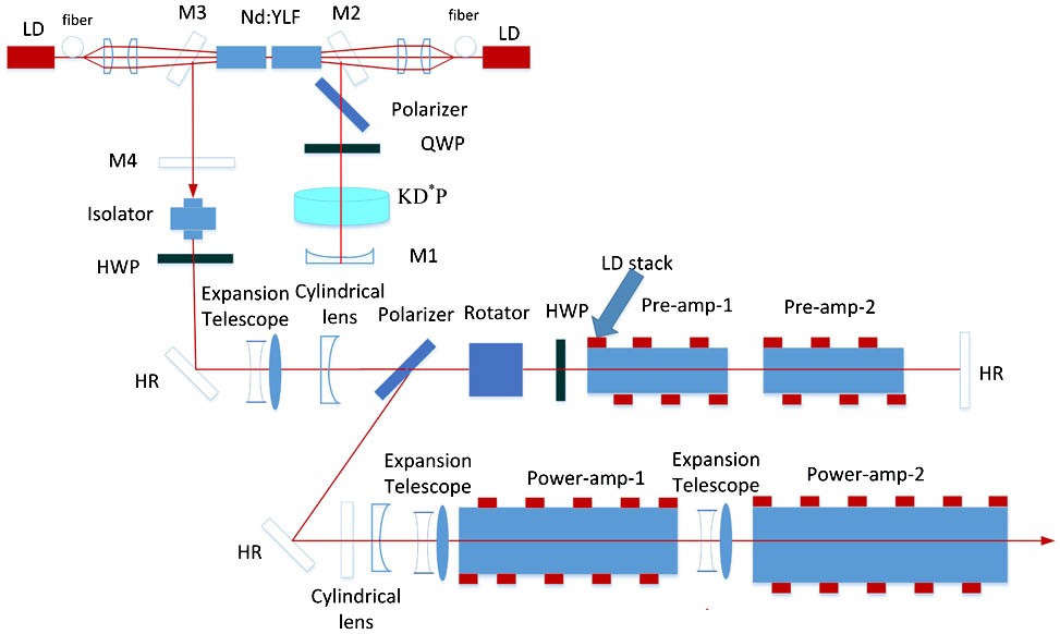
The schematic of the experimental setup is shown in Fig. 1. The oscillator used a U-type cavity to make the construction compact. The gain materials, including the oscillator and amplifier, employed a-cut Nd:YLF crystals. Although utilizing the c-cut Nd:YLF crystals as a gain medium for generating a 1053 nm lasers is more convenient[21,22], the isotropic property of these crystals in the transverse plane typically results in nonlinear polarization. To address this problem, a-cut Nd:YLF crystals can alternatively be employed to obtain a linearly polarized outputs. The folded resonator consisted of a high-reflectivity mirror M1 with curvature radius of 2000 mm; two flat, high-reflectivity mirrors M2 and M3 () at 1053 nm with high transmission at 806 nm wavelength; and a flat output coupler M4 with the transmission of 60% at 1053 nm. A polarizer, a quarter-wave plate, and a KD*P Pockel cell were used as the electro-optic -switch. The total length of the folded cavity was 620 mm.
Sign up for Chinese Optics Letters TOC. Get the latest issue of Chinese Optics Letters delivered right to you!Sign up now

Figure 1.Schematic of the experimental setup.
The oscillator was followed by a high-power Faraday isolator to prevent unwanted back-reflection from the amplifier. The amplification stage involved two double-pass pre-amplifiers, and two single-pass power amplifiers. The double-pass amplification structure included a polarizer, a Faraday rotator, and a high-reflectivity mirror M5. Without these devices, the pre-amplifier can operate in single-pass mode. The beam sizes of the signal were controlled with the use of expansion telescopes to ensure the optimal matching between the signal and the pump distribution of the amplifier. The following dimensions of the slab crystals were selected: for pre-amplifier, for Power Amplifier 1, and for Power Amplifier 2. To suppress parasitic oscillation, the Nd:YLF slabs were cut at a 3° angle. The pump and cooling architectures of the amplifier stage are shown in Fig. 2. The pumping LD array module was operated at a repetition rate of 50 Hz, with a pulse width of 400 μs. Each LD array included four (pre-amplifier) or six (power amplifier) LD bars. The highly divergent outputs and large beam divergence from a LD array present significant challenges to researchers in search of highly efficient but simple optical devices that can couple with the output from a LD array into a gain medium. To overcome these problems, many researchers have applied lens ducts to shape the pump laser[23,24]. However, lens ducts often present low coupling efficiency and large sizes. Thus, we designed a trapezoid waveguide to couple the pump laser. The dimensions of the waveguide were accurately calculated by ray tracing. The thickness of the waveguide in our experimental work was either 5 or 6 mm, the space between the waveguide and LD array, as well as that between the waveguide and slabs was less than 1 mm. This configuration makes the coupling system compact. The coupling efficiency of the waveguide is measured to be approximately 99%, which is significant larger than the coupling efficiency of the lens ducts.
Figure 2.Pump and cooling architecture of the amplifier.
The thermal lens effect in our experimental work differs from the simulation result in Ref. [25]. In the experimental work, the thermal lens in the vertical direction is negative, but that of the horizontal direction is positive. We believe that this result is due to the negative thermo-optical coefficient of Nd:YLF and the cooling architecture adopted. The temperature gradient of the slab in the vertical direction is substantial, and the thermo-optical effect is greater than the end-face effect, thereby leading to the negative thermal lens of the vertical direction. In contrast, the temperature gradient of the slab in the horizontal direction is weak, and the end-face effect is greater than the thermo-optical effect, thereby leading to the positive thermal lens along the horizontal direction. Cylindrical lenses were used to compensate for the thermal lens effect in the two directions.
The output characteristics of the oscillator in the quasi-CW (QCW) and -switched modes are shown in Fig. 3. At 95 mJ incident pump pulse energy, the oscillator gave out energies of 24 and 16 mJ at the output mirror in QCW and -switched modes, respectively. The respective corresponding conversion efficiencies at these modes were 25.2% and 16.8%, and the corresponding slope efficiencies were 34.0% and 21.1%, respectively. The optical spectrum performance of the master oscillator is shown in Fig. 4; the linewidth was 0.22 nm, and the center wavelength was 1053.38 nm.
Figure 3.Output characteristics of the oscillator versus pump energy in the QCW and -switched modes.
Figure 4.Optical spectrum of the Nd:YLF master oscillator.
The output pulse from the master oscillator was amplified by a four-stage side-pumped amplifier. We used double-pass pre-amplifiers to increase the extraction efficiency. The output energies at the pre-amplifiers during single-pass and double-pass amplification are shown in Fig. 5. With pump energy of 1757 mJ, the maximum output energy of the single-pass amplification was 75 mJ, and the output energy of the double-pass amplification was 165 mJ. The optical-to-optical efficiency of the pre-amplifier during single-pass amplification was 3.4%, whereas the optical-to-optical efficiency during the double-pass amplification was 8.5%. By employing the double-pass amplification structure, the optical to optical efficiency was markedly enhanced. Simulation results of the whole amplification system based on the Frantz–Nodvik (F–N) equation and variations in amplified pulse energy as a function of LD pump energy are shown in Fig. 6. Overall, two lines obtained fit very well. As the maximum output energy was approached, the experimental results decreased to values less than the simulation results. We believe that this phenomenon is a serious thermal effect that leads to low efficiency. The maximum output pulse energy of 655 mJ was extracted from the amplifier chain while the input signal pulse energy was around 16 mJ with 11.8 ns pulse width from the oscillator. The total absorbed pump pulse energy reached 6.6 J, corresponding to an optical-to-optical efficiency of 9.7%.
Figure 5.Output energies at the pre-amplifier during single-pass and double-pass amplification.
Figure 6.Output energy after the amplifier as a function of pump energy and the simulation based on the F–N equation.
The temporal trace of laser pulse from the master oscillator was detected and shown in Fig. 7(a). After amplification, the amplified pulse width was widened because of saturation effects during amplification process. The final pulse width of 12.9 ns was shown in Fig. 7(b), corresponding to a maximum peak power of 51 MW. To evaluate the spatial properties of the laser beam from the amplifier, the beam quality of the laser was measured with a Spiricon -200 laser beam analyzer. When the laser worked at the maximum pulse energy output, and were measured as 7.0 and 4.6, as shown in Fig. 8. The far-field laser beam profile of intensity distribution was detected and is shown in Fig. 9. The intensity of the beam was well-distributed but became non-Gaussian in shape because of the high-order thermal aberration. In our future work, we will optimize the dimension of the slabs and the sizes of the laser beam to improve the beam quality. Even more, by carrying out more accurate compensation for the lens effect, the beam quality can be further improved. The degree of line polarization exceeded 99%, due to the natural birefringence of the gain crystal. The system can safely operate without any damage for extended periods of time. In our experimental work, when a nonlinear crystal LiB3O5 with size of was used for the extra-cavity frequency doubling, more than 400 mJ of 527 nm green laser pulse was generated, the conversion efficiency was up to 60%.
Figure 7.Temporal trace of laser pulse: (a) pulse from the oscillator; (b) pulse from the amplifier.
Figure 8.Beam quality measurement of the MOPA system (50 Hz, 655 mJ pulse energy).
Figure 9.Far-field beam intensity distribution after amplification.
In conclusion, we propose a high-energy Nd:YLF slab MOPA laser system at 1053 nm wavelength. A double-pass pre-amplifier is employed to increase the extraction efficiency of this system. At the repetition rate of 50 Hz, the maximum output pulse energy of 655 mJ at 1053 nm with pulse width of 12.9 ns is obtained from the MOPA system. This MOPA laser system can also be utilized to generate high-energy green laser pulse at 526.5 nm wavelength. Pulsed compact green laser with high pulse energy is needed for underwater laser communication applications.
References
[1] W. Krichbaumer, H. Herrmann, E. Nagel, R. Häring, J. Streicher, C. Werner, A. Mehnert, T. Halldorsson, S. Heinemann, P. Peuser, N. P. Schmitt. Opt. Laser Technol., 25, 283(1993).
[2] D. Kracht, S. Hahn, R. Huss, J. Neumann, R. Wilhelm, M. Frede, P. Peuser. Proc. SPIE, 6100, 610021(2006).
[3] P. Peuser, W. Platz, P. Zeller, T. Brand, M. Haag, B. Köhler. Opt. Lett., 31, 1991(2006).
[4] M. E. Kushina, M. G. Grote, C. E. Wiswall, D. A. Hall, J. B. Russek. Proc. SPIE, 2379, 137(1995).
[5] T. D. Cole, M. Boies, A. El-Dinary. Proc. SPIE, 2748, 122(1996).
[6] W. Koechner. Solid-State Laser Engineering(2006).
[7] A. V. Okishev, W. Seka. IEEE J. Sel. Top. Quantum Electron., 3, 59(1997).
[8] S. Li, X. Ma, H. Li, F. Li, X. Zhu, W. Chen. Chin. Opt. Lett., 11, 071402(2013).
[9] H. Yang, J. Meng, X. Ma, W. Chen. Chin. Opt. Lett., 12, 121406(2014).
[10] X. Ma, J. Wang, J. Zhou, X. Zhu, W. Chen. Appl. Phys. B, 103, 809(2011).
[11] Z. Zhang, Q. Liu, M. Gong. Laser Phys. Lett., 10, 035002(2013).
[12] K. Du, D. Li, H. Zhang, P. Shi, X. Wei, R. Diart. Opt. Lett., 28, 87(2003).
[13] X. Yan, Q. Liu, L. Huang, Y. Wang, X. Huang, D. Wang, M. Gong. Laser Phys. Lett., 5, 185(2008).
[14] Q. Liu, X. Yan, M. Gong, X. Fu, D. Wang. Opt. Express, 16, 14335(2008).
[15] W. A. Clarkson, P. J. Hardman, D. C. Hanna. Opt. Lett., 23, 1363(1998).
[16] A. Dergachev, P. F. Moulton. Advanced Solid-State Photonics(2004).
[17] V. Bagnoud, M. J. Guardalben, J. Puth, J. D. Zuegel, T. Mooney, P. Dumas. Appl. Opt., 44, 282(2005).
[18] D. Li, Z. Ma, R. Haas, A. Schell, P. Zhu, P. Shi, K. Du. Opt. Lett., 33, 1708(2008).
[19] T. Lu, J. Ma, M. Huang, Q. Yang, X. Zhu, W. Chen. Chin. Phys. Lett., 31, 074208(2014).
[20] S. Liu, L. Dong, B. Zhang, J. He, Z. Wang, J. Ning, R. Wang, X. Liu. Chin. Opt. Lett., 12, 031402(2014).
[21] J. M. Auerbach, R. L. Schmitt. Opt. Lett., 16, 1171(1991).
[22] S. D. Pan, J. L. He, Y. E. Hou, Y. X. Fan, H. T. Wang, Y. G. Wang, X. Y. Ma. IEEE J. Quantum Electron., 42, 1097(2006).
[23] R. Fu, G. Wang, Z. Wang, E. Ba, G. Mu, X. Hu. Appl. Opt., 37, 4000(1998).
[24] G. Feugnet, C. Bussac, C. Larat, M. Schwarz, J. P. Pocholle. Opt. Lett., 20, 157(1995).
[25] C. Pfistner, R. Weber, H. P. Weber, S. Merazzi, R. Gruber. IEEE J. Quantum Electron., 30, 1605(1994).