
Jin ZHU, Xiaoyu PENG, Siyuan LUO, Wancheng XIAO, Lie HE, Yuchen LIU, Fengjiao LUO, Min XIAO, Xiaodong WANG. Performance of the electromagnetic calorimeter module in the NICA-MPD based on Geant4[J]. NUCLEAR TECHNIQUES, 2023, 46(12): 120202
- NUCLEAR TECHNIQUES
- Vol. 46, Issue 12, 120202 (2023)
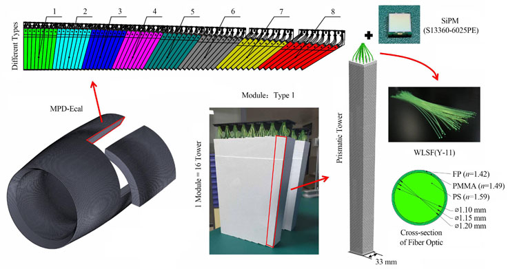
Fig. 1. Schematic diagram of the structure of the electromagnetic calorimeter

Fig. 2. Electromagnetic calorimeter unit (a) Schematic diagram of Tower structure, (b) Distribution of scintillator layer
Fig. 3. Working principle of electromagnetic calorimeter (a) Module model, (b) Luminescence decay curve, (c) Simplified model of electromagnetic shower, (d) Photon transmission process
Fig. 4. Influence of incident position on module performance (a) Eight different electron incident positions, (b) Influence of incident position on energy deposition, (c) Influence of incident position on energy resolution
Fig. 5. Effect of scintillator layer number on module performance (a) Scintillator layer vs. thickness of lead, (b) Effect of scintillator layer on energy deposition, (c) Effect of scintillator layer on energy resolution
Fig. 6. Material parameters vs. energy resolution (a) Relationship between the number of scintillator layers and energy resolution, (b) Relationship between the thickness of lead and energy resolution
Fig. 7. Time resolution simulation (a) Schematic diagram of the simulation scenario, (b) Time distribution of SiPM detected photoelectrons
Fig. 8. Simulation results of time resolution (a) Effect of scintillator layers on tower time resolution, (b) Effect of incident electron energy on tower time resolution
Fig. 9. Effect of polishing on detector performance (a) Influence of optical fiber end face polishing on the number of photoelectrons detected by SiPM, (b) Influence of optical fiber end face polishing on the time resolution of tower
Fig. 10. Cosmic ray test (a) Simulation scheme for cosmic ray testing, (b) Photoelectric yield, (c) Distribution of time difference between Tower and A, (d) Distribution of time difference between Tower and B, (e) Distribution of time difference between A and B
Fig. 11. Coordinate resolution simulation (a) 7×7 tower combination, (b) Energy deposition distribution of array towers
Fig. 12. Correction of the reconstructed position of the electrons (a) Electronic position reconstruction, (b) Energy deposition distribution around the point of incidence, (c) Reconstruction position error vs. incident position, (d) Calibrated electronically
Fig. 13. Simulation results of coordinate resolution (a) Effect of scintillator layer number on coordinate resolution, (b) Effect of incident electron energy on coordinate resolution
| ||||||||||||||||
Table 1. Main parameter of the materials


Set citation alerts for the article
Please enter your email address

© Copyright 2018-2021 | Chinese Laser Press. All Rights Reserved 沪ICP备15018463号-20