
Guang Feng, Zhihui Chen, Yang Wang, Xin Liu, Yinshan Liu, Xiao Liu, Fei Sun, Yibiao Yang, Shuqi Chen, "Enhanced Fano resonance for high-sensitivity sensing based on bound states in the continuum," Chin. Opt. Lett. 21, 031202 (2023)
- Chinese Optics Letters
- Vol. 21, Issue 3, 031202 (2023)
Abstract
1. Introduction
Terahertz (THz) sensing has become a promising technique because of its low energy and fingerprint for molecules[1–3]. However, the sensitivity of THz sensing is limited due to the mismatch between the relatively long wavelengths of THz waves and the analyte sizes. Recently, metasurfaces have been used to overcome this limitation.
A number of THz absorbers and metamaterial-based refractive-index sensing have been reported, such as metal-dielectric-metal configuration[4], planar structures based on breaking symmetry[5], and graphene-based structures[6-9]. Metamaterial THz absorbers are very sensitive to the changes of the refractive index of the surrounding medium. The THz absorber can achieve high sensitivity of 3.5 THz/RIU due to its cavity coupling to realize large-area field enhancement[10]. This strong field enhancement between light with a microstructure[11–13] allows for enhanced detection accuracy. Therefore, strong field enhancements are essential for high-sensitivity refractive-index label-free sensors[14–16]. Moreover, THz absorbers of high-order resonant frequency can also achieve high sensitivity of 4.72 THz/RIU[17]. This is because the frequency shift of the high order is larger than that of the lower order. For refractive index sensors, sensitivity and figure of merit (FOM) are two important indicators. To evaluate the actual performance of refractive index sensors, the FOM defined by the ratio of sensitivity to full width at half-maximum (FWHM) is used, which means the high-performance sensor requires not only considerable sensitivity but also a high quality (Q) factor[18]. Although previously reported, many THz absorbers can achieve high-sensitivity refractive index sensing, the resonant peak is too broad, which leads to a low Q factor and FOM. Therefore, strong sensitivity does not ensure peak distinguishability if the resonant peak is too broad.
For transmissive sensors in the THz band, it is difficult to achieve high-sensitivity refractive index sensing due to small-area and low-field enhancement. Recently, owing to Fano resonance having a high Q and strong field enhancement, the refractive index sensor based on Fano resonance has been studied[19]. Moreover, the Fano resonance of metasurfaces has also been linked to the bound states in the continuum (BIC)[20–24] to obtain high Q. High Q is often accompanied by a strong field enhancement. Therefore, there has been much research on Fano resonance based on BIC to improve the sensitivity of refractive indices[25–28]. However, the field enhancement is not proportional to the Q factor due to material dissipation[29]. Most of the research based on BIC is to achieve a refractive index sensing by obtaining a high Q factor[25,26,28]. Therefore, although the structure with the high Q factor can obtain high FOM, it cannot obtain the strongest local field enhancement[20], which limits the high sensitivity. In addition, the interaction between the field and the analyte is reduced due to the small-area local-field enhancement. Therefore, the reported transmissive sensors based on BIC is difficult to achieve more than 1 THz/RIU in previous work. To enhance the interaction between light field and analyte, strong local-field enhancement and large-area local enhancement play an important role in improving refractive index sensitivity.
Sign up for Chinese Optics Letters TOC. Get the latest issue of Chinese Optics Letters delivered right to you!Sign up now
Here, the Fano resonance of quasi-BIC is realized by tuning the length of triple copper rods. The Fano resonance with high Q and strongest near-field enhancement can be simultaneously obtained when the length of triple copper rods is 55 µm, and the multiple resonant structures can achieve multiple hot spots. The strong field and multiple hot spots are important in highly sensitive refractive index label-free sensors. Therefore, the theoretical sensitivity and FOM are, respectively, calculated to 1877 GHz/RIU and 665.
2. Structure and Methods
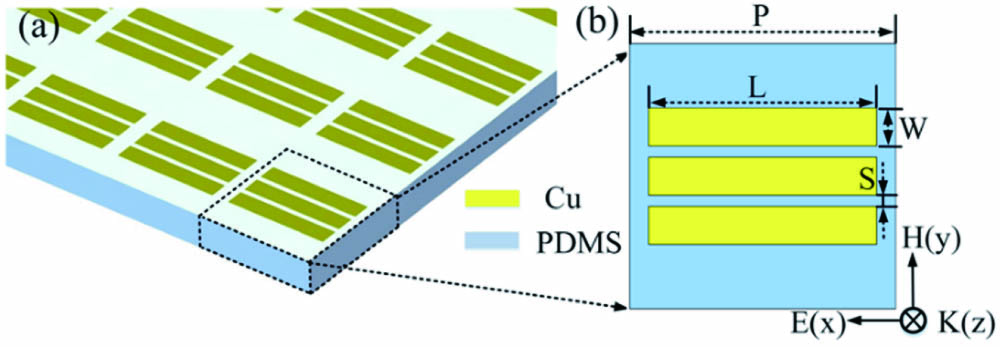
Figure 1(a) shows the designed triple metal rods structure, and Fig. 1(b) is a plan view of the periodic structure unit. Triple parallel metal bars have a length of L, the width of the metal strips is
![]()
Figure 1.(a) Three-dimensional structure diagram; (b) plan view of structure unit.
Although we only study in simulation, the potential feasible preparation method is shown in Fig. 2. The structure can be fabricated by a standard optical lithography process. The detailed procedure of fabrication is illustrated in Fig. 2. The metal structure is fabricated on a PDMS substrate with a 20 µm thick layer and a refractive index of 1.4. First, radio-frequency magnetron sputtering is used to deposit a 200 nm thick copper film on the substrate. Subsequently, the 1 µm thick layer of positive photoresist is coated on copper film. Before lithography, we dry the photoresist to prevent the photoresist layer from deforming in the lithography process. Then, samples are prepared by photolithography and reactive ion etching. Finally, we can obtain the structure by using lift-off technology.
![]()
Figure 2.Fabrication for the proposed structure.
3. Results and Discussion
Figure 3(a) shows the transmission spectrum obtained by tuning the length L of the triple metal bars. The length L is from 50 to 70 µm. When the length L is 60 µm, the Fano resonance with a frequency of around 3.9 THz will disappear in Fig. 3(b). To prove that the resonance obtained is Fano resonance, the Fano linear formula is given[26]:
![]()
Figure 3.(a) Color plot of the transmission spectra with different lengths of metal bars; (b) transmission when the lengths of the metal bars are from 50 to 66 µm; (c) fitting curve of Fano resonance when the length of L is 56 µm; (d) transmission of MICMT and simulation when the lengths of the metal bars are 62, 60, and 58 µm, respectively. By curve fitting, the decay time of the internal losses, respectively, are about τ10 = 4000 fs, τ20 = 8000 fs, and τ30 = 500 fs. The decay time of coupling and the total coupling phases, respectively, are about τ1 = 400 fs, τ2 = 8000 fs, τ3 = 250 s, φ1 = 0.2π, φ2 = −0.3π, φ3 = −0.1π; τ1 = 400 fs, τ3 = 250 s, φ1 = 0.2π, φ3 = −0.1π; τ1 = 400 fs, τ2 = 8000 fs, τ3 = 250 s, φ1 = 0.2π, φ2 = −0.3π, φ3 = −0.1π. (e) Quadrupole modes and (f) dipole modes when the lengths of the metal bars are 55 µm.
Since the BIC is sensitive to geometric sizes, it can be determined that this is accidental BIC. The formation of BIC in Fig. 3(b) is the consequence of destructive interference between two radiating channels with different optical behaviors: the quadrupole and dipole modes in Figs. 3(e) and 3(f). In the vicinity of the BIC point, the quadrupole mode exhibits sharp linewidths; in contrast, the dipole mode shows a wide resonance spectrum, which leads to strong radiative losses[30]. It is well known that for a system with two different resonance phenomena continuously changing with the parametric variation, at one particular set of parameters, there may occur an avoided crossing through which both the modes can interact and interfere destructively, resulting in the vanishing of one of the modes[31]. The avoided crossing of two different resonances is the feature of forming Friedrich–Wintgen BIC (FW-BIC).
Figure 3(d) is the transmission spectrum when the lengths of the three metal bars are 62, 60, and 58 µm, respectively; the Q factor is 1186,
In Fig. 4, we investigated the effect of single, double, and triple metal bars on the FWHM, Fano intensity, Q, and
![]()
Figure 4.(a) Single, double, and triple metal bars structure unit; (b) FWHM under different lengths; (c) ratio of Fano intensity to FWHM under different lengths; (d) Fano intensity, Q factor, and Q × I under different lengths.
To obtain the maximum field enhancement, we investigate the electric and magnetic fields at different lengths in Fig. 5. As the simulations in Figs. 5(a) and 5(b) show, the resonances of the electric field and magnetic field enhancement disappear when the length is 60 µm. With the length L decreasing, the electric field enhancement increases. For the highest Q factor when the length is 59 µm, the electric field and magnetic field enhancements are not obvious. The maximum electric field enhancement of 71 and magnetic field enhancement of 0.12 are achieved when the length is 55 µm in Figs. 5(c) and 5(d). Meanwhile, the highest
![]()
Figure 5.Simulated field enhancement of the triple metal bars. (a) and (b) show color plots of the field enhancement for different lengths in the triple metal bars, respectively; (c) electric field enhancement and (d) magnetic field enhancement for the lengths of 53, 55, 59, and 60 µm in the triple metal bars, respectively; (e) electric field enhancement and (f) magnetic field enhancement corresponding to the green dotted lines in (a) and (b), respectively.
It is known that field enhancement is known to be proportional to
In addition, the electric field, magnetic field, and surface current distribution of the structure with lengths of 59, 55, and 50 µm is investigated in Fig. 6. The three dimensions, respectively, represent the maximum Q,
![]()
Figure 6.(a), (d), (g) Electric, (b), (e), (h) magnetic fields, and (c), (f), (i) surface current at the Fano resonance. (a), (b), (c) The length is 59 µm; (d), (e), (f) the length is 55 µm; (g), (h), (i) the length is 50 µm.
The strong field and multiple hot spots are all very important for highly sensitive refractive index label-free sensors. The enhancement of the electromagnetic field and multiple hot spots can lead to enhanced interaction between the electromagnetic field and the specific analyte, which can achieve high refractive index sensitivity for application in the biological and biochemical fields. The refractive index sensor is calculated in Fig. 7. An analyte layer is selected to be added to the structure. By varying the refractive index from 1.3 to 1.6 at a thickness of 70 µm, the Fano resonance peak is redshifted from 3.41 to 2.85 THz in Fig. 7(a). The linear relationship of Δf−n can be observed in Fig. 7(c), and the sensitivity S can be obtained by calculating the corresponding derivative of the Δf−n curve. Theoretical refractive index sensitivity can be defined as the ratio of the resonance peak frequency shift to the refractive index change. The refractive index sensitivity is 1877 GHz/RIU. This result is higher than other reported work in Table 1. In addition, the thickness of the analyte layer also affects the frequency shift. It can be seen from Fig. 7(b) that at a fixed refractive index of 1.6, the frequency shift
| Structure | Index Sensitivity | FOM | Year |
|---|---|---|---|
| Two silicon cuboids | 465.74 GHz/RIU | 2022[ | |
| Double metal split ring resonators | 455.7 GHz/RIU | 2019[ | |
| Three gold blocks | 165 GHz/RIU | 2021[ | |
| Double metal split ring resonators | 775.7 GHz/RIU | 284 | 2022[ |
| Triple metal rods | 1877 GHz/RIU | 665 | This work |
Table 1. Properties of BIC-Based Metasurface Sensors
![]()
Figure 7.(a) Dependence of transmission on the refractive index increased from 1.3 to 1.6 under the thickness of 70 µm; (b) dependence of transmission on the analyte thickness increased from 10 to 70 µm under the refractive index of 1.6; (c) frequency shift under different refractive indices of analyte extracted from (a); (d) frequency shift under different analyte thicknesses extracted from (b).
Meanwhile, the resonance characteristics have been investigated with the oblique incidence of TM. The simulated transmission of the triple metal bar of 55 µm length with oblique incidence (0° to 25°) of TM is displayed in Fig. 8(a). There is an obvious symmetry-protected BIC (SP-BIC) and FW-BIC that can be produced when the TM angle is 0° and 16.5°, respectively. The SP-BIC is formed due to the oblique incidence of the TM, resulting in symmetry breaking[39]. From Figs. 8(b) and 8(c), it can be found that the resonance disappears due to the mode crossing of Mode 1 and Mode 2. The crossing and avoided crossing of resonance modes both are typical features of FW-BIC. Therefore, BIC can also be realized here by adjusting the incidence angle, which provides a new manipulation method for the application.
![]()
Figure 8.Angular response for the triple metal bar length of 55 µm: (a) simulated transmission contour plot under TM-polarized incidence; (b) simulated transmission curves with incidence angles from 10° to 24°; (c) field distribution of Mode 1 and Mode 2 at 10° and 24°, respectively.
4. Conclusions
Due to the mutual coupling between the resonators, the triple parallel metal bars structure can realize the FW-BIC. By tuning the structural parameters of triple rods, the high Q, strong field, and multiple hot spots can be obtained when the length of metal bars is 55 µm. Moreover, the sensitivity and FOM are calculated to 1877 GHz/RIU and 665, respectively. Compared to the previously reported transmissive sensors based on BIC, the sensitivity has been greatly improved. An angular scan can achieve the SP-BIC and FW-BIC, which provides a new manipulation method. Therefore, the Fano resonance structure with strong field and multiple hot spots achieves high sensitivity refractive index sensing for application in the biological and biochemical fields.
References
[1] M. Nejat, N. Nozhat. THz fingerprints of cement-based materials. IEEE Sens. J., 19, 10490(2020).
[2] S. Ding, J. Y. Ou, L. H. Du, L. G. Zhu, S. A. Khan, H. Y. Chen, J. F. Zhu. Enhancing ultra-wideband THz fingerprint sensing of unpatterned 2D carbon-based nanomaterials. Carbon, 179, 666(2021).
[3] J. S. Dolado, G. Goracci, E. Duque, P. Martauz, Y. Zuo, G. Ye. THz fingerprints of cement-based materials. Materials, 13, 4194(2020).
[4] R. Yahiaoui, A. C. Strikwerda, P. U. Jepsen. Terahertz plasmonic structure with enhanced sensing capabilities. IEEE Sens. J., 16, 2484(2016).
[5] I. Al-Naib. Biomedical sensing with conductively coupled terahertz metamaterial resonators. IEEE J. Sel. Top. Quantum Electron., 23, 4700405(2017).
[6] F. Zangeneh-Nejad, R. Safian. A graphene-based THz ring resonator for label-free sensing. IEEE Sens. J., 16, 4338(2016).
[7] Y. Huang, S. C. Zhong, Y. C. Shen, L. G. Yao, Y. J. Yu, D. X. Cui. Graphene/insulator stack based ultrasensitive terahertz sensor with surface plasmon resonance. IEEE Photonics J., 9, 5900911(2017).
[8] M. Biabanifard, S. Asgari, S. Biabanifard, M. S. Abrishamian. Analytical design of tunable multi-band terahertz absorber composed of graphene disks. Optik, 182, 433(2019).
[9] G. Feng, Z. H. Chen, X. W. Wang, X. Liu, F. Sun, Y. B. Yang. Ultra-broadband terahertz absorber based on double truncated pyramid structure. Mater. Today Commun., 31, 103624(2022).
[10] X. Hu, G. Q. Xu, L. Wen, H. C. Wang, Y. C. Zhao, Y. X. Zhang, D. R. S. Cumming, Q. Chen. Metamaterial absorber integrated microfluidic terahertz sensors. Laser Photonics Rev., 10, 962(2016).
[11] Z. H. Chen, Y. Wang, Y. B. Yang, N. Qiao, Y. C. Wang, Z. Y. Yu. Enhanced normal-direction excitation and emission of dual-emitting quantum dots on a cascaded photonic crystal surface. Nanoscale, 6, 14708(2014).
[12] Z. H. Chen, N. Qiao, Y. B. Yang, H. Ye, S. D. Liu, W. J. Wang, Y. C. Wang. Enhanced broadband electromagnetic absorption in silicon film with photonic crystal surface and random gold grooves reflector. Sci. Rep., 5, 12794(2015).
[13] Z. H. Chen, N. Qiao, Y. Wang, L. Liang, Y. B. Yang, H. Ye, S. D. Liu. Efficient broadband energy absorption based on inverted-pyramid photonic crystal surface and two-dimensional randomly patterned metallic reflector. Appl. Energy, 172, 59(2016).
[14] L. H. Du, J. Li, Q. Liu, J. H. Zhao, L. G. Zhu. High-Q Fano-like resonance based on a symmetric dimer structure and its terahertz sensing application. Opt. Mater. Express, 7, 1335(2017).
[15] Y. B. Zhang, W. W. Liu, Z. C. Li, Z. Li, H. Cheng, S. Q. Chen, J. G. Tian. High-quality-factor multiple Fano resonances for refractive index sensing. Opt. Lett., 43, 1842(2018).
[16] L. Zhou, J. Zhou, W. Lai, X. D. Yang, J. Meng, L. B. Su, C. J. Gu, T. Jiang, E. Y. B. Pun, L. Y. Shao, L. Petti, X. W. Sun, Z. H. Jia, Q. X. Li, J. G. Han, P. Mormile. Irreversible accumulated SERS behavior of the molecule-linked silver and silver-doped titanium dioxide hybrid system. Nat. Commun., 11, 1785(2020).
[17] M. Karthikeyan, P. Jayabala, S. Ramachandran, S. S. Dhanabalan, T. Sivanesan, M. Ponnusamy. Tunable optimal dual band metamaterial absorber for high sensitivity THz refractive index sensing. Nanomaterials, 12, 2693(2022).
[18] L. Liang, X. Hu, L. Wen, Y. H. Zhu, X. G. Yang, J. Zhou, Y. X. Zhang, I. E. Carranza, J. Grant, C. P. Jiang, R. S. Cumming, B. J. Li, Q. Chen. Unity integration of grating slot waveguide and microfluid for terahertz sensing. Laser Photonics Rev., 12, 1800078(2018).
[19] K. L. Shih, P. Pitchappa, L. Jin, C. H. Chen, R. Singh, C. Lee. Nanofluidic terahertz metasensor for sensing in aqueous environment. Appl. Phys. Lett., 113, 071105(2018).
[20] X. G. Zhao, C. X. Chen, K. Kaj, I. Hammock, Y. W. Huang, R. D. Averitt, X. Zhang. Terahertz investigation of bound states in the continuum of metallic metasurfaces. Optica, 7, 1548(2020).
[21] A. I. Ovcharenko, C. Blanchard, J. P. Hugonin, C. Sauvan. Bound states in the continuum in symmetric and asymmetric photonic crystal slabs. Phys. Rev. B, 101, 155303(2020).
[22] S. Han, L. Q. Cong, Y. K. Srivastava, B. Qiang, M. V. Rybin, A. Kumar, R. Jain, W. X. Lim, V. C. Achanta, S. S. Prabhu, Q. J. Wang, Y. S. Kivshar, R. Singh. All-dielectric active terahertz photonics driven by bound states in the continuum. Adv. Mater., 31, 1901921(2019).
[23] L. Q. Zhu, S. Yuan, C. Zeng, J. S. Xia. Manipulating photoluminescence of carbon G-center in silicon metasurface with optical bound states in the continuum. Adv. Opt. Mater., 8, 1901830(2020).
[24] Y. K. Srivastava, R. T. Ako, M. Gupta, M. Bhaskaran, S. Sriram, R. Singh. Terahertz sensing of 7 nm dielectric film with bound states in the continuum metasurfaces. Appl. Phys. Lett., 115, 151105(2019).
[25] T. C. Tan, Y. K. Srivastava, R. T. Ako, W. H. Wang, M. Bhaskaran, S. Sriram, I. Al-Naib, E. Plum, R. Singh. Active control of nanodielectric-induced THz quasi-BIC in flexible metasurfaces: a platform for modulation and sensing. Adv. Mater., 33, 2100836(2021).
[26] R. Wang, L. Xu, J. Y. Wang, L. Sun, Y. N. Jiao, Y. Meng, S. Chen, C. Chang, C. H. Fan. Electric Fano resonance-based terahertz metasensors. Nanoscale, 13, 18467(2021).
[27] S. Romano, G. Zito, S. Torino, G. Calafiore, E. Penzo, G. Coppola, S. Cabrini, I. Rendina, V. Mocella. Label-free sensing of ultralow-weight molecules with all-dielectric metasurfaces supporting bound states in the continuum. Photonics Res., 6, 726(2018).
[28] W. Y. Cen, T. T. Lang, J. F. Wang, M. Y. Xiao. High-Q Fano terahertz resonance based on bound states in the continuum in all-dielectric metasurface. Appl. Surf. Sci., 575, 151723(2021).
[29] J. W. Yoon, S. H. Song, R. Magnusson. Critical field enhancement of asymptotic optical bound states in the continuum. Sci. Rep., 5, 18301(2015).
[30] S. Zhang, G. C. Li, Y. Q. Chen, X. P. Zhu, S. D. Liu, D. Y. Lei, H. G. Duan. Pronounced Fano resonance in single gold split nanodisks with 15 nm split gaps for intensive second harmonic generation. ACS Nano, 10, 11105(2016).
[31] S. Joseph, S. Sarkar, S. Khan, J. Joseph. Exploring the optical bound state in the continuum in a dielectric grating coupled plasmonic hybrid system. Adv. Opt. Mater., 9, 2001895(2021).
[32] Q. H. Wang, B. T. Gao, M. Raglione, H. X. Wang, B. J. Li, F. Toor, M. A. Arnold, H. T. Ding. Design, fabrication, and modulation of THz bandpass metamaterials. Laser Photonics Rev., 13, 1900071(2019).
[33] S. L. Li, Y. L. Wang, R. Z. Jiao, L. L. Wang, G. Y. Duan, L. Yu. Fano resonances based on multimode and degenerate mode interference in plasmonic resonator system. Opt. Express, 25, 3525(2017).
[34] S. Y. Li, Y. Y. Zhang, X. K. Song, Y. L. Wang, L. Yu. Tunable triple Fano resonances based on multimode interference in coupled plasmonic resonator system. Opt. Express, 24, 15351(2016).
[35] L. Q. Cong, M. Manjappa, N. N. Xu, I. Al-Naib, W. L. Zhang, R. Singh. Fano resonances in terahertz metasurfaces: a figure of merit optimization. Adv. Opt. Mater., 3, 1537(2015).
[36] Z. Hu, L. J. Yuan, Y. Y. Lu. Resonant field enhancement near bound states in the continuum on periodic structures. Phys. Rev. A, 101, 043825(2020).
[37] X. Yan, M. S. Yang, Z. Zhang, L. J. Liang, D. Q. Wei, M. Wang, M. W. Zhang, T. Wang, L. H. Liu, J. H. Xie, J. Q. Yao. The terahertz electromagnetically induced transparency-like metamaterials for sensitive biosensors in the detection of cancer cells. Biosens. Bioelectron., 126, 485(2019).
[38] X. Chen, W. H. Fan, X. Q. Jiang, H. Yan. High-Q toroidal dipole metasurfaces driven by bound states in the continuum for ultrasensitive terahertz sensing. J. Light. Technol., 40, 2181(2022).
[39] S. I. Azzam, K. Chaudhuri, A. Lagutchev, Z. Jacob, Y. L. Kim, V. M. Shalaev, A. Boltasseva, A. V. Kidishev. Single and multi-mode directional lasing from arrays of dielectric nanoresonators. Laser Photonics Rev., 15, 2000411(2021).


Set citation alerts for the article
Please enter your email address

© Copyright 2018-2021 | Chinese Laser Press. All Rights Reserved 沪ICP备15018463号-20