Key Laboratory of Intelligent Optical Sensing and Manipulation of the Ministry of Education & National Laboratory of Solid State Microstructures & College of Engineering and Applied Sciences & Institute of Optical Communication Engineering & Nanjing University-Tongding Joint Lab for Large-Scale Photonic Integrated Circuits, Nanjing University, Nanjing 210023, China
【AIGC One Sentence Reading】:We demonstrate programmable photonic RF filters using an integrated Fabry-Pérot laser with a saturable absorber, achieving high reconfigurability, reduced size, and complexity.
【AIGC Short Abstract】:We introduced programmable photonic RF filters using an integrated Fabry-Pérot laser with a saturable absorber. This approach simplifies the system and enhances performance, achieving a record-high tap number, wide tuning range, and high out-of-band rejection, paving the way for compact and versatile photonic RF filters.
Note: This section is automatically generated by AI . The website and platform operators shall not be liable for any commercial or legal consequences arising from your use of AI generated content on this website. Please be aware of this.
Abstract
We propose and experimentally demonstrate the programmable photonic radio frequency (RF) filters based on an integrated Fabry–Pérot laser with a saturable absorber (FP-SA). Owing to the high output power and the relative flatness spectrum of the FP-SA laser, only a waveshaper and an erbium-doped fiber amplifier (EDFA) were needed, which can greatly reduce the complexity of the system. The sinc filter employed 87 taps, representing a record-high tap number and resulting in a 3-dB bandwidth of 0.27 GHz and a quality factor of 148. Furthermore, Gaussian apodization enabled the out-of-band rejection of the filter to reach 34 dB and the center frequency to be finely tuned over a wide range, spanning from 4 to 14 GHz. These results indicate that the proposed scheme could provide a promising guideline for the photonic RF filters that demand both high reconfigurability and greatly reduced size and complexity.
Microwave photonic signal processing harnesses the advantages of photonics to perform tasks comparable to conventional microwave signal processing while also offering additional benefits such as low loss, high bandwidth, immunity to electromagnetic interference (EMI), tunability, and reconfigurability[1–5]. Many key functions have been realized, such as those reliant on radio frequency (RF) time delays, including phased array antennas, microwave photonic RF filters, analog-to-digital or digital-to-analog conversion, and arbitrary waveform generation[6–10]. Other functionalities include RF spectrometers, high-fidelity microwave tone generation, and many others[11–13]. Among these, photonic RF filters are one of the most basic and commonly used components, which can provide flexible and efficient signal processing capabilities in the microwave domain. By converting microwave signals into optical signals, they can take advantage of the large bandwidth and low-loss characteristics of optical systems. Photonic RF filters have exhibited versatile applicability, encompassing signal filtering, equalization, and noise suppression. They can be designed to have reconfigurable characteristics, allowing for dynamic adjustments tailored to the system’s specific requirements.
Several approaches have been used for photonic RF filters, such as mapping the optical filters’ responses onto stimulated Brillouin scattering. This approach maps the desired frequency response of an electrical filter onto the frequency response of an SBS-based optical filter. By adjusting the parameters of the optical filter, such as the fiber length and pump power, the desired RF filtering characteristics can be obtained. This approach has demonstrated impressive RF resolution, achieving exceptionally high levels of up to 32 MHz, and offers a remarkable stopband rejection performance, surpassing 55 dB[14].
Another key approach for photonic RF filtering involves transversal filters[15–20]. In this approach, the RF signal is converted to the optical domain, where weighted and progressively delayed replicas of the signal are generated. These replicas are then combined using photodetection. The tap weights of the transversal filter are adjusted to achieve RF transfer functions. The flexibility of transversal filters makes them appealing for implementing advanced adaptive and dynamic RF filters. With the ability to adjust tap weights in real-time, they can easily adapt to changing RF filtering requirements. Traditionally, discrete laser arrays or Bragg grating arrays have been used to provide the necessary taps[21,22]. However, these approaches have limitations, including increased complexity and reduced performance due to the limited number of available taps.
Sign up for Chinese Optics Letters TOC. Get the latest issue of Chinese Optics Letters delivered right to you!Sign up now
An emerging approach that is garnering attention involves utilizing integrated optical Kerr frequency comb sources. These sources offer a novel and powerful method by providing highly coherent multiple-wavelength channels with precise control over frequency spacing. Recently, a photonic RF filter with up to 80 taps, based on a 49 GHz spaced micro-comb source, has been achieved[23]. However, a power-consumption pump laser and complex control units for the Kerr micro-comb are needed. Moreover, an additional optical amplifier is also required due to the low optical power. Therefore, a compact, energy-efficient, and electronic-driving multi-wavelength light source should be ideal for microwave photonic signal processing. Using the passively mode-locked laser (PMLL) is the preferred approach for generating multiple wavelength sources. It is commonly achieved by incorporating into the laser cavity a saturable absorber (SA). Moreover, PMLL’s wavelength spacing can also be controlled by changing the laser cavity length.
Here, we propose and experimentally demonstrate a programmable photonic RF filter based on an integrated Fabry–Pérot laser with an intracavity saturable absorber (FP-SA) for the first time, to the best of our knowledge. We fabricated the FP-SA laser with a length of 1000 µm, which corresponds to the wavelength spacing of 42.5 GHz. Under the injection current of 140 mA and reverse voltage of , the output power of the FP-SA laser is above 20 mW. With this FP-SA laser, a photonic RF transversal filter was realized with a record number of wavelengths or RF “taps”, featuring 87 wavelengths. This is the highest number so far reported for RF transversal filters enabled by a 42.5 GHz free-spectral-range integrated FP-SA source. Furthermore, Gaussian apodization enabled the out-of-band rejection of the filter to reach 34 dB and the center frequency to be finely tuned over a wide range, spanning from 4 to 14 GHz. Moreover, owing to the high output power and the relative flatness spectrum of the FP-SA laser, only a waveshaper and an erbium-doped fiber amplifier (EDFA) were needed, which can greatly reduce system complexity. Compared to the Kerr micro-comb, the monolithically integrated FP-SA laser eliminates the pump laser and optical amplifiers, which can decrease hardware complexity and power consumption. The demonstrated performance suggests that the proposed scheme is a strong candidate for photonic RF transversal filters.
2. FP-SA Laser Design
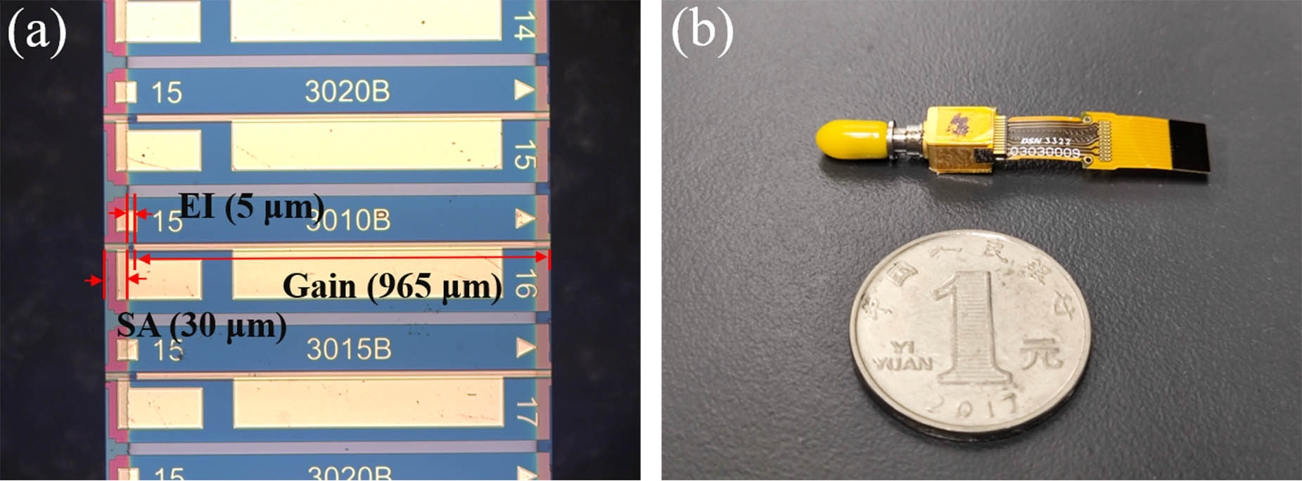
Figure 1(a) depicts the microscopic image of the proposed FP-SA laser, which consists of a gain region, an SA region, and an electrical isolation (EI) region. The SA section side facet is coated with a reflection of 95%, while the gain section side facet is coated with a reflection of 30%. The FA-SA laser with a length of 1000 µm was designed, which corresponds to the wavelength spacing of 42.5 GHz. The device was fabricated in the EPIHOUSE, a commercial InP foundry in China. The epitaxial wafer structure consists of an substrate, a buffer layer, two separate confinement heterostructure (SCH) layers, strained multiple quantum wells (MQWs) with compressive strain quantum wells (QWs) and tensile strain quantum barriers (QBs), an InGaAsP grating layer, and a cladding layer. Then, the chip was further box packaged, which is shown in Fig. 1(b). The box packaging protects the delicate chip from environmental factors and ensures the stable operation of the FP-SA laser.
Figure 1.(a) Microscopic image of the fabricated FP-SA chip and (b) the box packaged FP-SA laser.
Figure 2(a) shows the measured power-current (P-I) curves of the laser under 25°C controlled by the thermoelectric cooler. In the measurement, the reverse voltages of the SA region were set as 0 V and , respectively. The currents injected into the gain region varied from 0 to 150 mA. Owing to the increased interband and exciton absorption, an increase in the SA reverse voltage in the FP-SA laser causes an increase in the threshold current and a reduction in the slope efficiency. Under the reverse voltage and injection current of and 140 mA, the output power of the laser is above 20 mW. Figures 2(b) and 2(c) show the measured lasing spectra of the FP-SA laser under 25°C controlled by the thermoelectric cooler. The lasing optical spectra were recorded by the AQ6370 optical spectrum analyzer. When the reverse voltage of the SA region is 0 V, this is a normal Fabry–Pérot laser, whose optical spectrum is shown in Fig. 2(b). By properly tuning the reverse voltage, the FP-SA laser operates at the pure mode-locking regime with the reverse voltage of , whose optical spectrum is shown in Fig. 2(c).
Figure 2.(a) Power-current curves under different reverse voltages of the SA region. (b) Optical spectrum under the injection current of the gain region and the reverse voltage of the SA region of 140 mA and 0 V, respectively. (c) Optical spectrum under the injection current of the gain region and the reverse voltage of the SA region of 140 mA and −2.4 V, respectively.
RF transversal signal processors (RFTSPs) are built upon the classical transversal filter structure and find widespread applications in signal-processing tasks[24]. The key advantage of implementing RFTSPs with photonic technologies is that it can overcome the electrical bandwidth bottleneck commonly encountered in traditional electronic signal processing systems[25]. Photonic technologies operate at much higher frequencies than their electronic counterparts, enabling them to process signals with significantly increased bandwidth. The impulse response of the photonic RFTSP is represented by where is the number of taps, () represents the tap weight of the th tap, and is the time delay between adjacent taps. The output RF signal can be obtained by convolving the input RF signal with the impulse response from Eq. (1), where is the input RF signal. After performing the Fourier transformation on Eq. (1), we obtain the spectral transfer function of the photonic RFTSPs, denoted as , where is the angular frequency of the input RF signal. The Nyquist frequency of the filter is given by , where is the sampling period. By applying the calculated tap coefficients () on each wavelength channel, it is possible to implement programmable photonic RF filters with arbitrary spectral transfer functions. This programmability allows for versatile and flexible signal processing, making the photonic RFTSP suitable for various RF applications where precise control over the frequency response is required.
The photonic RF filter setup based on the proposed FP-SA laser is illustrated in Fig. 3. First, the spectrum of the FP-SA laser was shaped by the waveshaper to obtain the designed tap weights. The RF signal is then amplified by an erbium-doped fiber amplifier (EDFA). Next, the RF signal is imposed on the shaped spectrum through an intensity modulator. This step generates an optical representation of the RF input waveform, effectively converting the signal into the optical domain. To introduce wavelength-dependent delays, the modulated signal is transmitted through approximately 4.31 km of standard single-mode fiber (SMF). The dispersion of the SMF was ∼17.4 ps/(nm · km), which corresponds to a time delay between adjacent wavelengths, giving the transverse filter an operating bandwidth (i.e., half of the Nyquist frequency, the ) of [23]. It is worth noting that by reducing the time delay (e.g., using shorter SMF spools), the operating bandwidth of the transverse filter can be expanded. However, this comes at the expense of reduced tuning resolution. Conversely, the maximum operating bandwidth of the transverse filter is constrained by the wavelength spacing. Significant crosstalk between adjacent wavelength channels (or taps) occurs in the RF operation above 21.25 GHz (half of the wavelength spacing of 42.5 GHz)[24]. To address this issue, FP-SA sources with larger wavelength spacing can be employed. However, this would result in fewer available wavelength lines or taps in the C-band. Therefore, a trade-off exists between the operating bandwidth and the number of taps available for filtering. Finally, the weighted and delayed signals are combined and converted back to the RF domain through optical detection. This conversion allows the filter to provide the desired RF filtering response based on the designed tap weights and wavelength-dependent delays, enabling the filter to perform accurate and precise RF signal processing.
An all-ones photonic RF filter using different tap numbers [i.e., ] was proposed and experimentally demonstrated. In the experiments, the spectra of the FP-SA laser were flattened using a waveshaper. Different tap numbers were chosen, ranging from 4 to 87, and the corresponding optical spectra were measured and compared, as shown in Fig. 4. To improve the accuracy of the flattened spectra, a real-time feedback control path was implemented. The optical spectrum was detected by an optical spectrum analyzer, and the measured spectra were compared with the ideal tap weights. This comparison generated an error signal, which was then fed back into the waveshaper to calibrate the system and achieve precise spectra.
Figure 4.Optical spectra of the shaped FA-SA laser corresponding to the tap weights of a sinc filter with different tap numbers.
The performance of the filter was evaluated using several key parameters. One important parameter was the 3-dB bandwidth of the filter (), which showed improvement as the number of taps increased. Additionally, the quality factor (), defined as the ratio of the center frequency to the 3-dB bandwidth ()[26], also increased as the tap number expanded. In Fig. 5, the RF response of the all-ones photonic RF filter was measured and characterized using a vector network analyzer (VNA). The results confirmed a significant increase in the as the number of taps in the filter increased from 4 to 87. As the number of taps increased from 4 to 87, the decreased from 2.51 GHz to 0.27 GHz. This means that there is a linear relationship between the tap number and the , while the significantly decreased with higher tap numbers, further verifying the significant enhancement of frequency selectivity or resolution (reflected by ) achieved by employing a large tap number. By using 87 taps, the maximum of the microwave filter was calculated to be approximately 148. This indicates that the proposed all-ones photonic RF filter with a larger number of taps offers superior frequency selectivity and resolution, making it well suited for various applications that demand precise RF signal processing.
Figure 5.Measured RF transmission spectra of the sinc filter with different tap numbers.
Next, a Gaussian apodization was applied to the sinc filter, which is shown in Fig. 6. This operation exploited the Fourier transform property of Gaussian apodization, convolving the sinc function with a Gaussian function in the RF domain. As a result, the sidelobes are highly suppressed. In the experiment, different root mean square widths () of the Gaussian function were used. As shown in Fig. 7, the out-of-band rejection of the sinc filter can be increased to 34 dB. Note that, the of the RF transmission spectrum seemingly increases when the is set to 5. This can be attributed to the reduction in the number of taps after using Gaussian apodization (), which can be seen in Fig. 6.
Figure 6.Optical spectra of the Gaussian-apodized sinc filter (σ, Gaussian factor).
To tune the response of the Gaussian-apodized sinc filter and shift its center frequency by a factor , a frequency shift can be applied to the filter’s impulse response. This shift will maintain the same FSR and overall shape as the original filter while centering it at the new frequency. By applying the -transform properties, the new spectral transfer function of the filter can be achieved, denoted as ,
Therefore, the new filter tap coefficients can be represented as . To demonstrate the tunability of the Gaussian-apodized sinc filter, the center frequency () can be varied from 4 to 14 GHz with a step size of 2 GHz. The resulting RF transmission spectra for different center frequencies are shown in Fig. 8. Importantly, this tunable Gaussian-apodized sinc filter can achieve optimized performance by merely reprogramming the tap weights without requiring physical tunable delay lines. This tunable characteristic is advantageous as it provides flexibility and ease of reconfiguration for various applications. By adjusting the tap coefficients, the filter can be dynamically adapted to different center frequencies, making it suitable for a wide range of RF signal processing tasks without the need for physically altering the filter’s hardware setup. This capability enhances the versatility and practicality of the Gaussian-apodized sinc filter in real-world scenarios where variable center frequencies are often encountered.
Figure 8.Measured RF transmission spectra of the center frequency-tunable Gaussian-apodized sinc filter.
In summary, a programmable photonic RF filter using a 42.5 GHz-FSR integrated FP-SA laser is proposed and experimentally demonstrated. A record number of wavelengths or RF “taps” (specifically 87 wavelengths) are used in the sinc filter, whose and can reach 0.27 GHz and 148, respectively. Gaussian apodization delivers a high out-of-band rejection of up to 34 dB. Furthermore, we also achieve a tunable center frequency covering the RF spectral range from 4 to 14 GHz. Thus, the FP-SA laser becomes a valuable tool in photonic RF signal processing due to its large number of wavelength channels, high optical power, relative flatness spectrum, and compact footprint.
[20] H. Sun, M. Khalil, D. V. Plant et al. Reconfigurable microwave photonics filters with negative coefficients based on a quantum dash mode-locked laser. IEEE International Topical Meeting on Microwave Photonics (MWP), 1(2021).
 AI Video Guide
  AI Picture Guide
 AI One Sentence